background image


Design, Development, Manufacturing, Installation of Gas 
Leak Alarm and Additional Service


Human Technology & Future 

INSTRUCTION MANUAL 

GTC-540 

Revision: 2 


GASTRON 


Copyright⒞  GASTRON, Co., LTD. All rights reserved. 

Please read this manual carefully for the correct use of the equip ment 

Summary of Contents for GTC-540

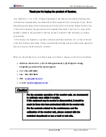
Page 1: ...stallation of Gas Leak Alarm and Additional Service Human Technology Future INSTRUCTION MANUAL GTC 540 Revision 2 GASTRON Copyright GASTRON Co LTD All rights reserved Please read this manual carefully for the correct use of the equipment ...

Page 2: ...maintenance methods etc for the control unit of the GTC 540 Gas Leak Alarm Please read carefully and keep well and it will provide great help when you have any doubt during the operation When any abnormality may occur after buying our products please contact to below address Address Gastron Co Ltd 18 8 Dogeumdanji 1 gil Palgok 2 dong Sangnok gu Ansan City Gyeonggi do Tel 031 490 0800 Fax 031 490 0...

Page 3: ...iver Unit and Detection Unit 11 6 Menu Table 12 7 Operation 14 7 1 Connection Check 14 7 2 Power ON 14 7 3 Gas Concentration Display 14 7 4 Password Input 15 7 5 Program Data Setting 15 7 6 Alarm Data Setting 17 7 7 Option Setting 20 7 8 Test Mode Setting 21 7 9 Maintenance Function Setting 22 7 10 Test Function Setting 24 7 11 DOWN Stand by Mode 24 7 12 Factory Initialization Function 25 7 13 Cal...

Page 4: ...has primary alarm secondary alarm and tertiary alarm function and failure alarm function 2 Structure GTC 540 Independent receiver unit displays the alarm with audio signal buzzer and visual signal Alarm LED and has the function to hold the maximum measured values when the alarm is activated Since GTC 540 receiver unit allows the remote control to reset alarm and has output for the alarm SPDT conta...

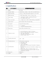
Page 5: ...0mA DC 2wire or 3wire 9 Output signal 4 20mA DC Isolated RS 485 Modbus Option 10 Reset signal Reset switch and remote control 11 Program set mode Set strength and type of alarm 1 2 3 alarm Set time of alarm immediate delayed 1 60 sec Alarm range Dead band Compensate the measured value SAD Set relay output to on off 12 Operating temperature 20 50 13 Operating humidity 0 99 RH non condensing 14 Oper...

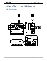
Page 6: ... 540 Instruction Manual PAGE 6 of 30 Rev3 2014 09 01 4 Name of Each Part and Major Function 4 1 Component 212 48 235 59 7 8 9 10 11 12 13 20 31 6 3 1 2 21 5 4 14 15 16 17 18 19 4 30 23 22 29 28 27 24 25 26 ...

Page 7: ... external shock 3 Mars light When alarm is activated Mars light is turned on 4 Mount hole 2 Ø6 5 This is the hole to fix the control unit to external wall or other mounting plate 5 Conduit connection 1 Ø16 5 5 Ø20 5 Total 6 holes of Ø16 5 and Ø 20 5 are made at the bottom Connect the power cable signal cable etc using the cable inlet according to the site condition 6 O Ring NBR Prevent the water f...

Page 8: ...f diagnosis is reset if the RESET S W is pressed 18 RESET S W It performs alarm reset self test reset program setting reset etc 19 BZ STOP S W When the alarm is activated it is used to stop the buzzer 20 Buzzer When the alarm and the trouble alarm are activated and test is performed The buzzer is sounded consecutively 21 Terminal Block Cover To supply the power to the product open the cover and co...

Page 9: ...ction Connect the AC power 85 260V 50 60Hz to CN7 as shown in figure In case of using DC24V it should be requested separately when ordering the product and when the DC24V type of product is delivered according to the user s request the positive of DC24V should be connected to L1 of CN7 and the negative to L2 ...

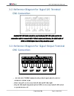
Page 10: ...th 4 20mA output and detector the shield cable of CVVS or CVVSB higher than 0 75sq should be used 5 3 Reference Diagram for Signal Output Terminal CN5 Connection AL1 AL2 AL3 TROUBLE display the relay contact signal when the alarm is activated or trouble occurs Alarm Lamp LP can be connected with External DC Mars light Only the Mars light designated by Head Office can be connected with CN4 which is...

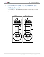
Page 11: ... 30 Rev3 2014 09 01 5 4 Connection between GTC 540 Receiver Unit and Detection Unit For the connection with detection unit the shield cable higher than 0 75 sq of CVVS or CVVSB is used mA DC18 31V mA ET DC18 31V mA 2Wire type ET 3Wire type ...

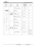
Page 12: ... 128 1 Pass Word 0 99 00 End U P D O W N ALARM MODE LACH U P D O W N ON OFF ON Energizer ON OFF OFF Alarm Lamp ON OFF ON Alarm 1 1 Full range 20 F R 1H H L H 1H 00 0 99 00 Alarm 1 Time Delay 0 60 1 Alarm 1 Relay ON OFF ON Alarm 1 Blink ON OFF OFF Alarm 2 1 Full range 40 F R 2H H L H 2H 00 0 99 00 Alarm 2 Time Delay 0 60 1 Alarm 2 Relay ON OFF ON Alarm 2 Blink ON OFF OFF Alarm 3 1 Full range 50 F R...

Page 13: ...R D I N P U T U P D O W N Option MODE Maintenance Level U P D O W N 0 Full range 0 Under ON OFF OFF Engineering ON OFF OFF Emergency Timeout ON OFF OFF End U P D O W N Test MODE Trouble Relay U P D O W N ON OFF OFF Alarm Relay ON OFF OFF mA out ON OFF OFF or 0 or 100 0 or 100 Flickering When it is set to ON start from 100 When it is set to OFF start from 0 ...

Page 14: ... above than Alarm 1 and below the Alarm 2 with orange and if the concentration is above than Alarm 3 it is displayed with red The value set to 3 step Alarm is always displayed with 3 Color bar graph LED and the value for Alarm 1 is displayed with green for Alarm 2 with orange and for Alarm 3 it is displayed with red When the detector is not connected or the value of current received from the detec...

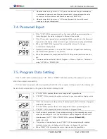
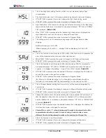
Page 15: ...tically When the RESET S W is pressed the mode will be returned to the gas concentration display mode Demand to enter password It is set to P00 when it is shipped from the factory P00 means that password is not entered When the password is entered and the FUNC SW is pressed each mode can be set The mode can be verified in order of Program Alarm Option Test mode using UP S W or DOWN S W If FUNC S W...

Page 16: ...s increased or decreased whenever UP S W or DOWN S W is pressed and when the value is negative it is displayed by adding sign in front of first number Default 0 If FUNC S W is pressed when the desired SAD value is displayed the SAD value is set and the screen is changed for next item If RESET S W is pressed the mode is returned to Program Mode Ex If the error of detector output is 2 although the a...

Page 17: ...arm latch type If RESET S W is pressed the mode is returned to the alarm setting mode This is mode to change the alarm reset type and On and OFF modes will be changed whenever UP S W or DOWN S W is pressed If FUNC S W is pressed when the desired Alarm Latch Type is displayed Alarm Latch Type is set and the screen is changed for next item If RESET S W is pressed the mode is returned to Alarm Settin...

Page 18: ...tration provide by domestic law when shipping This is the mode to set the direction of Alarm1 operation and H or L is displayed whenever UP S W or DOWN S W is pressed H mode is to activate when the gas value is equal or greater than the value set to Alarm 1 and L mode is to activate when the gas value is equal or below than the value set to Alarm If FUNC S W is pressed when the desired mode is dis...

Page 19: ... or OFF whenever UP S W or DOWN S W is pressed Alarm1 contact output mode has two modes of ON and OFF and Alarm 1 contact output is not activate in the OFF mode but in the ON mode If FUNC S W is pressed when the desired Alarm 1 contact output is displayed Alarm 1 contact output If RESET S W is pressed the mode is returned to Alarm Setting mode This is the function to set the Alarm 1 blink output w...

Page 20: ...ue is displayed the selection is set and the screen is changed for next item If RESET S W is pressed the mode is returned to Option Setting mode This is function to set of Undr is displayed in FND when the value is below than 10 out of the value less than 0 If FUNC S W is pressed the mode is changed to Under setting mode If RESET S W is pressed the mode is returned to Option Setting mode On or OFF...

Page 21: ...as the user can set the gas concentration by pressing UP S W or DOWN S W and Alarm function is operating normally with the concentration value set by the user If FUNC S W is pressed the mode is changed to Test Setting mode If RESET S W is pressed the mode is returned to the gas concentration display mode This is the mode to set Trouble Relay Test operation to ON OFF If FUNC S W is pressed the mode...

Page 22: ...t to display for one hour after manipulating final S W FUNC S W or RESET S W should be pressed to return to Test Setting mode This is the mode to select the input and output current values which are the basis of Channel Unit and In or oUt is displayed whenever UP S W or DOWN S W is pressed If FUNC S W is pressed when the desired mode is displayed and the screen is changed for relevant mode In is m...

Page 23: ...0mA output terminal and if press FUNC S W when the value of ampere meter and the value displayed in FND are same the output current is set and the screen is changed for next item If RESET S W is pressed the mode is returned to the gas concentration display mode This is the mode to set the 20mA output current Default 20 00 Due to display limit of FND the tens digit and decimal values are displayed ...

Page 24: ... more than 2 second to return to gas concentration display mode Full Range In Test mode the gas concentration is displayed flickering This mode is the function to be able to test the detector sensor in the Channel Unit without injecting gas the user can set the gas concentration by pressing Test S W and Alarm function is operated normally with the concentration value set by the user If FUNC S W is...

Page 25: ...C S W to enter to the mode Yes No can be selected with UP S W or DOWN S W and Yes is selected Factory Initialization function can be used Default No If RESET S W is pressed the mode is returned to the gas concentration display mode Since this is the function using FUNC S W it may occur the case that S W is pressed consecutively To prevent that if FUNC S W is operated when selecting Yes no in the F...

Page 26: ...is returned to the gas concentration display mode Enter to this mode by pressing FUNC S W Yes No can be selected with UP S W or DOWN S W and if Yes is selected Calibration Initialization can be used Default No If RESET S W is pressed the mode is returned to the gas concentration display mode Since this is the function using FUNC S W it may occur the case that S W is pressed consecutively To preven...

Page 27: ... 30001 BIT15 0 Measure gas value integer type Decimal Point is not considered High Scale value 30002 BIT15 0 High Scale value integer type Decimal Point is not considered Gas detector value 10000 BIT0 Alarm 1 Active BIT1 Alarm 2 Active BIT2 Alarm 3 Active BIT3 Maintenance Mode BIT4 Test Mode BIT5 Calibration Mode BIT6 Reserved BIT7 Toggle Bit Bit reversal in 2 Sec interval External Test 3 BIT0 7 S...

Page 28: ...GTC 540 Instruction Manual PAGE 28 of 30 Rev3 2014 09 01 9 Outside View and Dimensions ...

Page 29: ...GTC 540 Instruction Manual PAGE 29 of 30 Rev3 2014 09 01 ...

Page 30: ...Layout and add the functions Jan 15 2014 3 Add the functions Sep 01 2014 END This product and product manual are subject to change for the improvement of product performance and the convenience of use without prior notice Gastron Co Ltd Gastron Co Ltd 18 8 Dogeumdanji 1 gil Palgok 2 dong Sangnok gu Ansan City Gyeonggi do Tel 031 4900 800 Fax 031 4900 801 http www gastron com gastron gastron com ...

Reviews: