background image


Version : 9.0 


J5 & J5 LX Series 

Maintenance Manual 


Summary of Contents for J5 Series

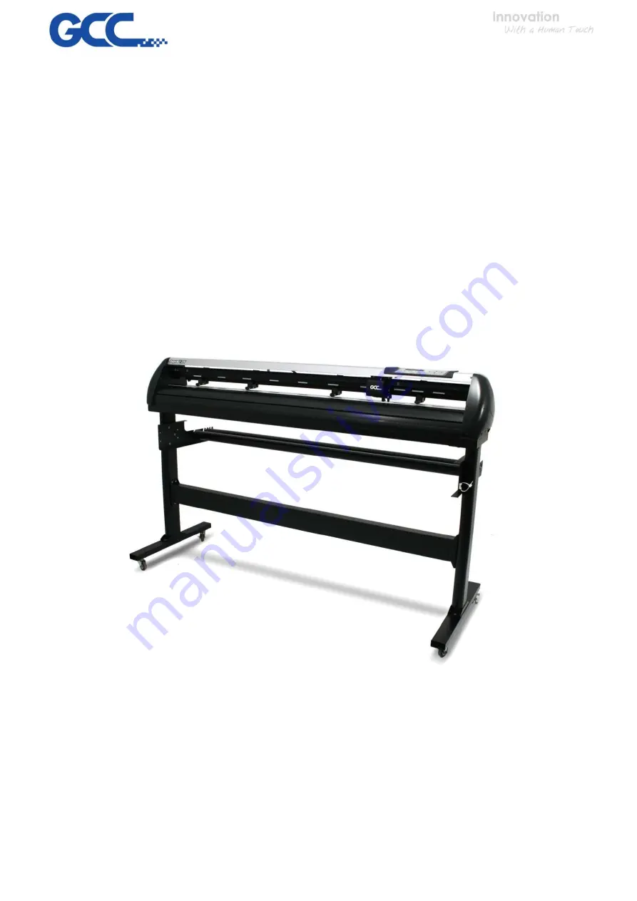
Page 1: ...Version 9 0 1 J5 J5 LX Series Maintenance Manual...

Page 2: ...placing the VCM PC Board 38 4 1 6 Main board Connectionor Replacement 39 4 1 7 Replacement of Fuses 39 4 1 8 Adjusting the Tool Carriage Transmission Belt 40 4 1 9 Adjusting the X Motor Tension Belt 4...

Page 3: ...Chapter 3 Circuit System there is detailed information for the connection circuits Chapter 4 Introduction to show you how to replace parts Chapter 5 Trouble shooting System Diagnostics Chapter 6 We ha...

Page 4: ...iagrams to show the part number for every part in the following sections They are Main unit Left End Assembly Right End Assembly X Motor Bracket and Belt Assembly Carriage Assembly LX Carriage Assembl...

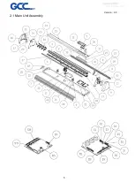
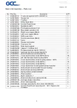
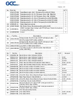
Page 5: ...Version 9 0 5 2 1 Main Unit Assembly...

Page 6: ...d5 t0 6 3 19 25200003G panhead machine screw white M3 8 2 20 25200006G Socket headness set screw M3 5L 1 21 25200115G Truss head machine screw M3 6L SUS 36 22 25200122G 90 dish flat head machine screw...

Page 7: ...TY Remark S1 209026810G Motor Driver cable 3 96 2pin 160mm 1 S2 20901915G Motor Driver cable 3 96 2pin 1100mm 1 J5 61 20901913G Motor Driver cable 3 96 2pin 1900mm 1 J5 132 20901912G Motor Driver cabl...

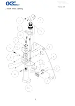
Page 8: ...Version 9 0 8 2 2 Left End Assembly...

Page 9: ...ket 1 7 24400526G Pully top bracket 1 8 24400755G Side support left 1 9 25200052G Pan head machine screw including spring washer 4 10 25200182G Truss head screw including external teech washer 2 11 25...

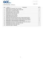
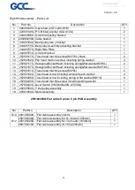
Page 10: ...Version 9 0 10 2 3 Right End Assembly 290106350G Flat cable 9 pin to 8 pin PCB Assembly...

Page 11: ...ng spring flat washer M3 8L 2 12 25200157G HexagonalSocketHead including spring flat washer M3 16L 1 13 25200181G Truss head machine screw M4 6L 2 14 25200182G Truss head screw including external teec...

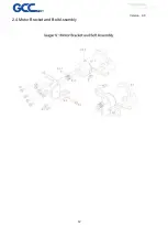
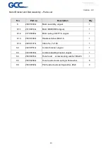
Page 12: ...Version 9 0 12 2 4 Motor Bracket and Belt Assembly...

Page 13: ...1 6 1 3 25200169G Headless Screw M4x3 5 1 6 1 4 22000107G Cable Tie YJ 160 1 6 2 24400761G X motor bracket Jaguar 1 6 3 24400038G X motor adjusting bracket Jaguar 1 6 4 25200245G Truss head screw spri...

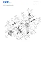
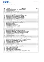
Page 14: ...Version 9 0 14 2 5 Carriage Assembly...

Page 15: ...2 18 24700044G O Ring d2 0 r1 5 1 19 25200004G Pan head machine screw M2 6 6L 2 20 25200008G Socket head set screw M3 6L while coating 2 21 25200017G Truss head machine screw M3 15L black 2 22 2520004...

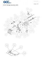
Page 16: ...Version 9 0 16 2 6 LX Carriage Assembly AAS...

Page 17: ...2 18 24700044G O Ring d2 0 r1 5 1 19 25200004G Pan head machine screw M2 6 6L 2 20 25200008G Socket head set screw M3 6L while coating 2 21 25200017G Truss head machine screw M3 15L black 2 22 252000...

Page 18: ...1050mm 1 290108320G Flat cable assembly for 132 model 1830mm 1 290108310G Flat cable assembly J5 183 2250mm 1 S13 20901523G AAS II Sensor PCB to carriage PCB 1 S16 20900128G Cable from VCM Encoder to...

Page 19: ...Version 9 0 19 2 7 Pinch Roller Assembly...

Page 20: ...31G Blocking arm shaft 1 7 24100142G Blocking arm 1 8 24100268G Pinch roller base 1 9 24100276G CAM roller 1 10 24100355G Pinch roller active arm 1 11 241005730G Sensor Sheet 1 12 26500080G Indexer fi...

Page 21: ...Version 9 0 21 2 8 Main Beam Assembly...

Page 22: ...Bracket 2 8 25200084G 90 dish flat head machine screw M2 6 6 25 9 25200093G Pan head machine screw M3 4L black 2 10 25200115G Truss head machine screw M3 6L SUS 4 11 25200208G Truss head screw includ...

Page 23: ...Version 9 0 23 2 9 Drum Assembly...

Page 24: ...Part No Description QTY 1 20700039G Grid Drum Bearing 10 2 22800407G Grid Drum shaft 1 3 22800564G Bearing Blocker 2 4 24100189G X axis actively belt gear 1 5 25200169G Socket headness set screw M4 3...

Page 25: ...Version 9 0 25 Chapter 3 Circuit System 3 1 System Diagram...

Page 26: ...Mainboard Port Connected to J5 Pinch Roller switch J8 20x2 Ribbon Cable connect to Motor Drive Board J10 J26 External Ethernet Port J32 Control Panel J33 External USB Port J41 20x2 Ribbon Cable connec...

Page 27: ...Motor encoder J5 Rear paper sensor J6 Front paper sensor J7 X Motor power J8 Y Motor power J9 DC Power input J10 20x2 Ribbon Cable connect to Main Board J8 J19 20x2 Ribbon Cable connect to Main Board...

Page 28: ...is machine 4 1 Components Replacement and Belt Tension Adjustment 4 1 1 Removing the Front Back End and Top Covers The following steps are those involved in removal of the front back end and top cover...

Page 29: ...9 To Remove the Top Cover Unscrew the two screws at each end of the Top Cover Remove the panel PCB cover screws and take out the cover Disconnect the grounding cable Disconnect control panel on the ma...

Page 30: ...ollowing steps are those involved in replacing pinch roller sets To Unlatch the Pinch Roller Lever Pull down the Square Bar Lever to unlatch the Pinch Rollers To Remove the Square Bar Holding Bracket...

Page 31: ...right end of the Square Bar Note When re installing the Pinch Roller Set the Cam Roller must be aligned squarely to the Square Bar Cam Roller Release Grip Note When aligning the Cam Roller please rem...

Page 32: ...ng are those you must follow to successfully replace the Tool Carriage To Loosen the Carriage Belt Retaining Screws Adjustment screw Unscrew the 2 retaining screws but don t remove them Then turn the...

Page 33: ...Version 9 0 33 To Remove the Tool Carriage cover Depress the two locking clips at the top of the Tool Carriage Cover and pull the Cover away...

Page 34: ...arriage for Removal Pop up the plastic locking pins using a flathead screwdriver Disconnect the Flat Sensor Cable Bolt A Bolt B Unbolt and remove nut A and B and then unscrew both Bolt A and Bolt B un...

Page 35: ...down and out while keeping the Sprung Washer Rollers apart Note 1 To install a new Tool Carriage or replace the original Tool Carriage simply reverse the steps for Tool Carriage removal 2 Remember to...

Page 36: ...replacement of the Y motor 1 Loosen the all 3 tension bracket retaining screws as well as the tension adjustment screw but do not remove them 2 Depress the jumper clips and pull to unplug the 2 3 Lif...

Page 37: ...ter the Y motor is in place you must adjust the Y motor belt tension as described in the Y motor belt tension adjustment section of this chapter Note 3 Make the Y motor jumper reconnection the last st...

Page 38: ...is what is involved in replacement of the VCM PC board Unplug the two sensor connectors then loose the two PC board screws to remove the board Note If the Pinch Roller Sensor is still not effective af...

Page 39: ...ty instruction at the beginning of this manual before installing or replacing any current carrying components 1 Unplug all of the jumpers and connectors attached to all of board components Note Please...

Page 40: ...de beam after the tool carriage or belt being replaced 2 Loosen the 2 retaining screws on top of the carriage belt roller housing 4 To change belt tension adjust the 5 To tighten the tension turn the...

Page 41: ...gauge s hook arm at the hole of X motor bracket and pull the motor toward yourself along the direction parallel to the racket edge and keep it at the 4kg tension position 3 Tighten the 4 retaining 4 F...

Page 42: ...t remove them 2 Place the push pull tension gauge s hook arm at the hole of Y motor bracket and pull the motor toward yourself along the direction parallel to the line that passes through the motor sh...

Page 43: ...Version 9 0 43 4 Tighten the tension screw to retain the tension Note The belt connecting the drive pulley and Y motor needs to be tightened up with a tension of 4 kg...

Page 44: ...Diagnostics Diagnostic test for the media sensors Diagnostic test for the width sensor Diagnostic test for the motor encoder and tool holder encoder Diagnostic test for Tool Force VCM Diagnostic test...

Page 45: ...w Key Pressed Down Arrow Key Pressed Carriage Goes Left Up Arrow Key Pressed Up Arrow Key Pressed Down Arrow Key Pressed Carriage Goes Right Up Arrow Key Pressed Down Arrow Key Pressed Check RS 232 Up...

Page 46: ...e pinch rollers have been lowered or not If the lever sensor is down you will see a lift the lever message on the LCM If the lever is up you will see a lower the lever message on the LCM You can use t...

Page 47: ...an turn it on or off to see if sensors are out of order or not Up Down Key Check Media Sensors Enter Key Pressed Cancel Key Previous Next Test item Display Current Sensor Condition Messages Change Sen...

Page 48: ...is is done please move the tool carriage to left Be careful when moving the tool carriage close to the pinch roller since the message changes quickly when sensor is between on and off Check Width Sens...

Page 49: ...ol carriage or the tool holder then examine the readings If the encoder reading changes dramatically the encoder is bad Refer to the maintenance chapter to replace the motor or tool carriage X Motor E...

Page 50: ...arriage cannot perform the up down action that generates the tools force on the material Note VCM means Voice Coil Motor that generates tool force 5 1 9 Diagnostic Test for Motor Movement This feature...

Page 51: ...us Next test item Carriage Goes Left Up Down Key Cancel Key Enter Key Y Motor Moving Now Forward CANCEL Previous Next test item Carriage Goes Right Up Down Key Cancel Key Enter Key Y Motor Moving Now...

Page 52: ...al state CancelKey Type any characters From Computer CANCEL No Type any character fromthe computer Error or not Yes Wait for 3 seconds The message you typed Error Messages Type character again Y ENTER...

Page 53: ...tation of the width sensor on the carriage PCB is not correct Adjust the orientation of the carriage PCB c The position of the width sensor on the carriage PCB is too high to sense the block bar on th...

Page 54: ...chip is bad Change it b Main board set is bad Change it 7 Fatal error occurs when loading media Causation and recovery a Forget to pull out some media from the media roll Pull out some media from the...

Page 55: ...e the Carriage set f The driver board set is damaged Change it g The linear bearing shaft of VCM is rusty Change the Carriage set h The two small bearings clamp the linear bearing shaft too tight Adju...

Page 56: ...Drum or pinch roller is worn Change the drum set or pinch roller 5 3 Firmware update Normally before a new machine or spare main board is ready to ship a loader or even a firmware will be uploaded fir...

Page 57: ...g Firmware and Uploader can be downloaded from GCC website http gccf gcc com tw distributor login aspx Step4 When firmware is updated completely LCM will show as below then factory default the machine...

Page 58: ...V 241006770G Rear platen extension 61 V V 290094072G Carriage assembly Jaguar V 183 LX V 290094062G Carriage assembly Jaguar V LX serial V V V 290094051G Carriage assembly Jaguar V serial V V V 290092...

Page 59: ...n extension 132 V V 241006990G Rear platen extension 160 241006750G Rear platen extension 183 V 241006770G Rear platen extension 61 V V 24100247G Right cover Jaguar Black V V V V V V V 24100246G Left...

Reviews: