background image

GE Digital Energy 

Power Quality 


SP_010-0

40_S8_U

PS_GE_0

1


Operating Manual 

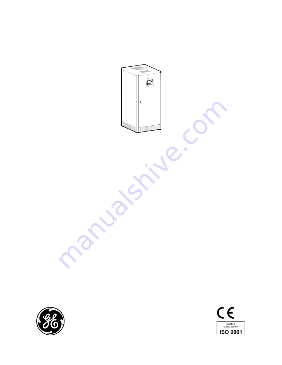
Uninterruptible Power supply 

Digital Energy™ 

SitePro 

10 – 15 – 20 – 30 – 40 kVA 

400 Vac CE   /   Series 8 


GE Consumer & Industrial SA 

General Electric Company 
CH – 6595 Riazzino (Locarno) 
Switzerland 
T +41 (0)91 / 850 51 51 
F +41 (0)91 / 850 51 44 


www.gedigitalenergy.com 


GE imagination at work 


Summary of Contents for 8 Series

Page 1: ...nual Uninterruptible Power supply Digital Energy SitePro 10 15 20 30 40 kVA 400 Vac CE Series 8 GE Consumer Industrial SA General Electric Company CH 6595 Riazzino Locarno Switzerland T 41 0 91 850 51 51 F 41 0 91 850 51 44 www gedigitalenergy com GE imagination at work ...
Page 2: ...008 by GE Consumer Industrial SA All rights reserved The information contained in this publication is intended solely for the purposes indicated The present publication and any other documentation supplied with the UPS system is not to be reproduced either in part or in its entirety without the prior written consent of GE The illustrations and plans describing the equipment are intended as general...

Page 3: ...he use of the SitePro Uninterruptible Power Supply system developed and produced to the highest standards of quality will give you complete satisfaction Please read carefully the Operating Manual which contains all the necessary information and describes all you need to know about the use of the UPS Thank you for choosing GE Distributed by Your service contact g GE Consumer Industrial SA General E...

Page 4: ... Product according to EN 50091 2 In a domestic environment this product may cause radio interference in which case the user may be required to take additional measures SitePro 30 40 kVA is a product for restricted sales distribution to informed partners Installation restrictions or additional measures may be needed to prevent disturbances We recommend that this manual be kept next to the UPS for f...

Page 5: ... PARALLELED ON THE SAME BATTERY 18 4 5 SERVICE AND TECHNICAL SUPPORT 19 4 6 WARRANTY 19 4 7 RECYCLING AT THE END OF SERVICE LIFE 20 5 INSTALLATION 21 5 1 TRANSPORT 21 5 1 1 Dimensions and weights 21 5 2 DELIVERY 22 5 3 STORAGE 22 5 3 1 Storage of the UPS 22 5 3 2 Storage of Battery 22 5 4 PLACE OF INSTALLATION 23 5 4 1 UPS location 23 5 4 2 Battery location 24 5 5 VENTILATION AND COOLING 25 5 6 UN...

Page 6: ...lete Parallel System shutdown 83 8 2 7 Restore to normal operation after Load Off 84 9 CUSTOMER INTERFACE 85 9 1 CUSTOMER INTERFACE 85 9 1 1 Serial Port J3 RS232 sub D female 9 pin 86 9 1 2 Serial Port J11 RS232 sub D female 9 pin Option 86 9 1 3 Output signals on voltage free contacts 87 9 1 4 Programmable input free contacts 87 9 1 5 EPO Emergency Power Off 88 9 1 6 Gen Set Signalling GEN ON 89 ...

Page 7: ...ectly reattached This UPS is intended for use in a controlled indoor environment free of conductive contaminants and protected against animals intrusion WARNING HIGH EARTH LEAKAGE CURRENT Earth connection is essential before connecting to AC input Switching OFF the unit does not isolate the UPS from the mains Do not install the UPS in an excessively humid environment or near water Avoid spilling l...

Page 8: ...he battery cabinet 2 Tools must have insulated handles and must be insulated so that they will not short battery terminals Do not allow a tool to short between individual or separate battery terminals or to the cabinet or rack Do not lay tools or metal parts on top of the battery and do not lay them where they could fall onto the battery or into the cabinet 3 Install the battery as shown on the dr...

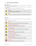
Page 9: ...TE Warns the user about important operations or procedures described in this manual Safety symbols When the text includes one or more of the following symbols that means exist a potentially hazardous situations Please remind the meaning of each symbol CAUTION Related to all the potentially hazardous situations which may result in injury DANGER OF PARTS ELECTRICALLY LIVE Related to all the situatio...

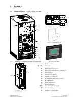
Page 10: ...Fig 2 1 1 Internal view with open door and without protection panels Fig 2 1 4 Control Panel 1 Electronic Module F8 F9 Battery fuses J11 RS232 Port for IMT Protocol LD1 Indicator for closure of battery fuses F8 F9 M1 Outlet grid fans P1 Power Interface Board P4 Customer Interface Board PA 24 Vdc Auxiliary Power Supply option Q1 UPS output switch Q2 Manual bypass switch Q4 Input rectifier switch SN...

Page 11: ...rs more real power than other UPS in the market With today s trend toward power factor corrected loads SitePro can support more total load than any other UPS available allowing you to support a greater number of today s enterprise computing Power Factor Corrected PFC equipment No single point of failure Redundant Parallel Architecture RPA is an exclusive GE technology With RPA SitePro UPS are cont...

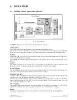
Page 12: ...age into a three phase AC voltage with constant amplitude and frequency which is completely independent and isolated from the AC input voltage Automatic Bypass The Automatic Bypass consists of a static semiconductor switch SSM Static Switch Module used to provide an uninterrupted transfer of the Load from Inverter to Mains Back feed Protection All SitePro UPS s are equipped with an automatic syste...

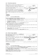
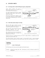
Page 13: ...he mains power is available the Load is normally powered through the Automatic Bypass When the mains voltage is detected out of the prescribed tolerances the Load is automatically transferred to the Inverter When the Mains recovers the Load returns to the Automatic Bypass after a variable time defined by the control unit Fig 4 2 2 1 Energy flow in SEM mode operation The SEM mode can be configured ...

Page 14: ...a Battery low warning occurs on a unit not necessary to support the present load this unit will shut down after a timeout period selectable The Load is shared between the other units As the warning occurs on one unit necessary to support the present load the system starts the stop operation timeout selectable The Load will shut down at the end of the stop operation time period 4 2 4 Mains recovery...

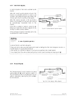
Page 15: ...ode an alarm condition will be initiated A Manual Bypass operator initiated will not be considered as an alarm condition Fig 4 2 5 1 Block diagram Automatic Bypass In case of parallel operation Each unit has its own internal Bypass These units are continuously exchanging information enabling all of the internal Bypass circuits in a Parallel System to operate simultaneously If the Inverter of a uni...

Page 16: ... circuitry see Fig 4 3 1 1 Parallel units for power capacity Several units can be paralleled in order to achieve output power greater than the maximum power of a single unit The maximum total power shared between the paralleled units is equal to the total installed nominal power In the event of a failure of one unit the power supplied by the UPS system becomes insufficient and the Load will be tra...

Page 17: ...h all other modules in order to act or react if necessary adapting to the new conditions 4 3 4 Synchronization All UPS units are identical but one unit is arbitrarily selected as the reference and all the other units synchronize to this unit which in turn synchronizes to the Mains Bypass voltage as long as the latter is within tolerances In case of reference failure another unit in the Parallel Sy...

Page 18: ...stallation The installation must be performed only with the UPS system must be completely shut down The AC rectifiers input power 5 must be the same with the right phase rotation for each unit Each rectifier must be set for the same floating DC voltage and the same battery current limitation It is mandatory to install the fuses MCB 7 on each line connecting the rectifiers to the common battery for...

Page 19: ...A Fig 4 5 1 Identification label The requested data permitting to identify your UPS are marked on the identification label fixed on the front of the cabinet behind the lower front door For fast and efficient technical support please mention the data marked on the identification label 4 6 WARRANTY GE operating through its authorised agents warrants that the standard products will be free of defects...

Page 20: ...s respecting eco design rules It does not contain CFCs Carbon Fluor Clorid or HCFCs Halogen Carbon Fluor Clorid GE in compliance with environment protection recommends to the User that the UPS equipment at the end of its service life must be recovered conforming to the local applicable regulations WARNING Leads contained in the batteries is a dangerous substance for the environment therefore it mu...

Page 21: ...ake all necessary precautions to avoid damage to the cabinet while hoisting the UPS Forklift Crane Fig 5 1 1 UPS cabinets moving NOTE Check for sufficient floor and elevator loading capacity 5 1 1 Dimensions and weights Dimensions SitePro 10 15 20 30 and 40 kVA W x D x H SP_010 040_S8_UPS dimensions_GE_01 1 450mm 57 08 680mm 26 77 800mm 31 49 680 x 800 x 1450 mm 26 77 x 31 49 x 57 08 inches Weight...

Page 22: ...st free room away from chemical substances and with a temperature range not exceeding 25 C 13 F to 55 C 131 F Some important functions of the UPS such as the customized functions are defined by parameters stored in a RAM memory A small backup Battery located on the Control Unit board supplies the RAM If the storage time of the UPS exceeds 1 year these functions should be verified by an authorized ...

Page 23: ...on of the battery supplier NOTE Temperature is very important for valve regulated batteries maintenance free Operation at temperatures higher than 77 F 25 C will reduce battery life A single phase power socket should be provided for connection of power tools test equipment or connectivity devices SP_010 040_S8_UPS disposition_GE_01 Min 400mm 16 500mm 20 200mm 8 Min Min Fig 5 4 1 1 SitePro 10 15 20...

Page 24: ... controlled temperature to obtain reliable operation The Battery can be install immediately adjacent to the UPS left or right side or remotely from the UPS If the Battery is installed remotely from the UPS a wall mounted DC disconnect device must be installed within line of site to both the UPS and the Battery The optimal room temperature for the Battery is 20 C 68 F to 25 C 77 F The life of valve...

Page 25: ...irflow for UPS cooling should enter from underneath the UPS through the appropriate aperture on the raised floor If the UPS runs in a dusty environment we recommend strongly to install filters on the air inlet of the UPS room In this case it should be considered that these filters can cause reduced speed at the air inlet The size of the air inlet has therefore to be dimensioned accordingly Contact...

Page 26: ...eavy weight of the equipment NOTE Be aware of the heavy weight of the UPS in particular if already equipped with Batteries Ensure that the cabinet is not damaged when moving by forklift White colour without any anomaly Red colour anomaly evidence Fig 5 6 1 ShockWatch device Fig 5 6 2 TiltWatch device The package of the SitePro is equipped with ShockWatch indicator for shock and TiltWatch indicator...

Page 27: ...rature 20 C If the battery cabinet is not mounted side by side the UPS the cable connecting the temperature sensor to the UPS should be run in a protective trunk or conduit NOTE If the battery distance from the UPS is 5 m we suggest do not use this circuit and the correct loading voltage must be installed manually according to the annual average temperature at which the battery will be working req...

Page 28: ...ectifier Bypass The same power source is to be used for both bypass supply and rectifier input input F3 Bear in mind that when the mains fuses are opened there is a supply failure to the rectifier as well as to the bypass and manual bypass switch In this case the interconnection links BR1 BR2 and BR3 on the input terminals MUST REMAIN CONNECTED Separate input Rectifier Bypass recommended The bypas...

Page 29: ...g the neutral current to be higher then the phase current Avoid to run the input cables in parallel with the output cables to prevent them from noise induction The three phase Mains power supply must be symmetrical with respect to earth due to the existence of voltage surge protection devices inside the UPS The connection of the Battery to the UPS must be protected with fuses or similar devices ac...

Page 30: ...andards EN UPS Model A B C E D K SitePro 10 kVA 4 x 4 mm2 4 x 2 5 mm2 5 x 4 mm2 5 x 2 5 mm2 3 x 6 mm2 SitePro 15 kVA 4 x 6 mm2 4 x 4 mm2 5 x 6 mm2 5 x 4 mm2 3 x 10 mm2 SitePro 20 kVA 4 x 10 mm2 4 x 6 mm2 5 x 10 mm2 5 x 6 mm2 3 x 10 mm2 SitePro 30 kVA 4 x 10 mm2 4 x 10 mm2 5 x 10 mm2 5 x 10 mm2 2x25 1x16 mm2 SitePro 40 kVA 4 x 16 mm2 4 x 10 mm2 5 x 16 mm2 5 x 10 mm2 2x25 1x16 mm2 Cables section mm2...

Page 31: ...0 30 40 kVA S8 5 7 3 Installation requirements Typical examples for the connection of the SitePro 10 40 kVA Single UPS with common input for rectifier bypass Single UPS with separate input for rectifier bypass UPS single unit with separate mains input for Rectifier and Bypass and galvanic separation ...

Page 32: ...reserved Page 32 99 OPM_SPE_XXX_10K_40K_8GB_V020 doc Operating Manual SitePro 10 15 20 30 40 kVA S8 UPS Parallel System with common input rectifier bypass UPS Parallel System with separate input for rectifier bypass ...

Page 33: ...minals SitePro 10 15 20 kVA 16mm2 SitePro 30 40 kVA 50mm2 Max rating F8 F9 terminals SitePro 10 15 20 kVA 50mm2 SitePro 30 40 kVA 50mm2 Separate input rectifier bypass BR1 BR2 and BR3 must be removed L1 1 Rectifier input L1 L2 1 Rectifier input L2 L3 1 Rectifier input L3 L1 2 Bypass input L1 L2 2 Bypass input L2 L3 2 Bypass input L3 N1 Neutral mains input PE Earth mains input L1 3 L2 3 L3 3 Used f...

Page 34: ...frequency converter mains input bypass terminals not powered with separate AC inputs following a complete power down the UPS system must be restarted only having the rectifier input terminals powered SitePro 10 15 20 30 40 kVA P1 SP_010 040_S6_lay front view P1_01 If the power source must be changed locally proceed as follows With the UPS completely switched OFF on the P1 Power Interface remove th...

Page 35: ...ormer magnetisation or motor starting Notices for start up operation Since the AC Power supply is fed from the input mains rectifier see Section 5 8 2 the control panel will be powered ON only after closing the input switch Q4 The lamp B1 BYPASS PHASE OK on P1 Power Interface see Section 5 8 2 for clockwise phase rotation check will stay OFF After closing the output switch Q1 the output will not y...

Page 36: ...o phase shift allowed between units NOTE It is strongly recommended that no transformers automatic circuit breakers or fuses should be inserted between the unit s output and the Load common bus bars However it is recommended that a disconnection or isolation switch is installed in order to totally isolate a unit if needed Verify that power wiring and control wiring run in separate conduits or cabl...

Page 37: ... should fail or be accidentally damaged or disconnected The standard length of the control bus cable between two parallel unit is 12 m 40 ft Maximal overall length of bus connection between the first and the last unit should not be longer than 84 m 276 ft Verify that control wiring is run in individual separate steel conduit NOTE Under no circumstance should the control bus cable connecting JA 1 2...

Page 38: ...umpers JP1 JP2 JP3 and JP4 must be inserted SP_010 300_S6_RPA IM0048_03 P3 P13 P11 JA 2 JB 2 JP2 IM 0048 JP1 JP4 JP3 JA 1 JB 1 JP1 JP2 JP4 JP3 J62 B A J52 Fig 5 9 2 3 Bus connection on intermediate units Intermediate units On the parallel bus PCB P34 Bus Interface IM0048 of the intermediate units of the Parallel System the Jumpers JP1 JP2 JP3 and JP4 must be removed NOTE In a Parallel System compo...

Page 39: ... 300_S6_RPA IM0048_04GB P3 P13 Next parallel unit JA JA 2 JA 1 JB 1 JB 2 F JB J52 A J62 B F Fig 5 9 3 2 Front view electronic module on intermediate unit P11 J62 B SP_010 040_S7_RPA IM0048_02 J52 A P13 P2 P3 Fig 5 9 3 3 Internal view electronic module Control bus cables connection Plug the cables JA 1 2 3 4 5 6 7 and JB 1 2 3 4 5 6 7 onto the RJ connectors JA and JB located on parallel bus PCB P34...

Page 40: ...ng and routing the bus cables JA and JB inside the UPS cabinet In case one unit should be removed from the Parallel System the bus cables JA and JB must be removed from the cabinet without disconnect them from the metal plate where are located the sockets JA and JB For reliability reasons the cables JA 1 2 3 4 5 6 7 and JB 1 2 3 4 5 6 7 connecting the units should be run in separated protected con...

Page 41: ... the UPS front door acts as the UPS user interface and comprises of the following elements Back lit Graphic Display LCD with the following characteristics Multilanguage communication interface English German Italian Spanish French Finnish Polish Portuguese Czech Slovakian Chinese Swedish Russian and Dutch Synoptic diagram indicating UPS status Command keys and parameters setting UPS status control...

Page 42: ...from the Load It is possible to activate the command Load Off using the following screen COMMANDS REQUEST LOAD OFF See Section 7 5 Attention Load Off cannot disconnect the UPS from the Load with Q2 closed Home Commands COMMANDS RESET LOAD OFF REQUEST LOAD OFF To reset Load Off Restore the command Load Off by entering the screen COMMANDS RESET LOAD OFF V For Parallel System if Load Off is pressed o...

Page 43: ...e load is not protected by UPS or in case Q1 is open LED Operation green colour When lit indicates that the UPS is functioning correctly and the load is system protected Load supplied either from inverter or from Automatic Bypass in case of SEM functionality When blinking indicates that a regular maintenance service is needed SERVICE REQUIRED May be reset by a service technician only See Section 1...

Page 44: ...customize some UPS functions to specific requirements and to view UPS identification data See Section 7 4 CMDS COMMANDS Allows the user to execute UPS operation commands See Section 7 5 The LCD screen after 5 minutes of inactivity shuts down the backlight To reactivate it it is sufficient to press any keys If the keypad remains inactive for 5 minutes or longer during the viewing of a screen such a...

Page 45: ...ate a load status at 25 LED A Indicates a load level between 26 and 50 LED A B Indicate a load level between 51 and 75 LED A B C Indicate a load level between 76 and 100 LED A B C D Indicate a load level between 101 and 124 LED D blinking Indicates a load level 125 Fig 7 1 2 LEDs on synoptic diagram LEDs on synoptic diagram LED 1 Input mains rectifier LED 2 Input mains bypass LED 3 Rectifier ON LE...

Page 46: ...ry data screen V The battery voltage I The battery current negative values correspond to the discharge of the battery T The temperature of the battery SENSOR DISABLE indicates sensor disabled Charge level The battery charge level Autonomy The estimated backup time with the present load Home Meter RECTIFIER f 50 0 Hz L12 397 V Vdc 409 V L23 395 V Idc1 41 0 A L31 393 V Idc2 0 0 A Rectifier mains dat...

Page 47: ...ERTER Load on phases screen 2 kW The load active power kW for RPA total value of Parallel System kVA The load apparent power kVA for RPA total value of Parallel System The output Load as percentage for RPA with respect to the rated power of Parallel System The source of the power supplied to the load Home Meter COUNTERS Bypass mains failure 53 Rectifier mains failure 35 Overloads 15 InvOperTime h ...

Page 48: ...y pushing the key for more than 3 seconds The events displayed are the standard GE events as described in the Section 7 3 1 EVENTS Alarms and Messages Home Alarm ALARM LEVEL 1 USER LEVEL 2 SERVICE V Alarms screen LEVEL 1 USER Chronologically view 2 events per screenshot LEVEL 2 SERVICE Chronologically view 5 events per screenshot with service related info Home Alarm User NR 255 01 06 2007 15 37 25...

Page 49: ...l JB 4008 BUS JA FAILURE There is an interruption in the channel JA of the parallel communication bus system 4009 BUS JB FAILURE There is an interruption in the channel JB of the parallel communication bus system 4010 CONNECTIVITY BUS FAILURE The connectivity communication bus is faulty or interrupted 4104 BATTERY FUSES FAILURE This function when enabled on input programmable relays password requi...

Page 50: ...nt limit causing the inverter Off and automatic re start After 3 times the inverter switches Off and it can be restarted manually 4321 HIGH CURRENT SHARING A high exchange current value is detected between the UPS of the parallel system 4340 INVERTER CONTROL FAILURE The Slave oscillator is not in synchrony with the Master thus causing the shutdown of it s inverter If after a restart the condition ...

Page 51: ...ransferred again automatically on inverter when load 100 4581 INVERTER AND MAINS NOT SYNCHRONIZED The voltages of mains and inverter are not synchronised which causes the opening of K6 4697 BATTERY OVERTEMPERATURE The battery temperature exceeds the value inserted in parameter Disabled with parameter service only 4698 BATTERY POWER INSUFFICIENT In case of mains failure with the actual load the run...

Page 52: ...ter 4302 INVERTER CANNOT BE TURNED ON Inverter cannot be switched on because one of the following conditions is still present Overtemperature Low battery voltage Inverter fuses Overload K7 opening failure High battery voltage DC low EPO 4303 INVERTER CANNOT BE TURNED OFF Inverter cannot be switched OFF because the load cannot be switched to mains voltage out of tolerance not synchrony BP blocked 4...

Page 53: ...K 4411 or setting parameters 4600 COMMAND UPS ON The SEM mode function has been disabled or the programmed time is expired The UPS returns to VFI mode supplying the load normally by inverter 4601 COMMAND UPS STANDBY The function SEM mode is enabled and according to the time program the UPS will run in SEM mode supplying the load normally by mains 4602 Q1 OPEN The auxiliary contact indicates that t...

Page 54: ... __ __ Series No UPS rating kVA Customer Place Date Sent by 1 Record the exact UPS status on the panel when the failure appeared 2 On the LCD panel enter the alarms mode and record the alarms messages in the list below indicating at least 5 events before the failure time Remark exact data and time are very important Event No Event Code UPS Status Date Time h m s 255 254 LED 1 ON OFF 253 LED 2 ON O...

Page 55: ...ey to set or modify the parameters ESC Allows to exit a selected screen without making any modification U Scrolls backward to the previous line V Scrolls forward to the next line Allows to access a value to be set or modified Select on the same line the following value or letter to set or modify Set or modify the selected value Save the set or modified value and return to the selected screen It is...

Page 56: ...ith Y N the remote control through modem calls by using this parameter For modem connection the default setting is for serial port J3 on P4 Customer Interface Init This parameter presents the modem initialisation string It can be 40 characters long When editing this parameter the UPS considers that a blank character terminates the string If no blank character is found then all 40 characters are us...

Page 57: ... controls the baud rate used for data transmission Parity This parameter controls the parity used for data transmission Odd O even E and No Parity NO can be selected In case No Parity NO has been set automatically the parameter 8 bits is used independently of the value of Bits set Bits This parameter controls the length of the data word on the serial line during data transmission Handshake This pa...

Page 58: ...tically disabled if this condition is not satisfied In case this minimum time in VFI mode is not respected the SEM mode will be disabled If the value is N the UPS is normally operating in VFI double conversion mode at all times DAY OF WEEK d1 d7 Enabling time in function of weekdays For the weekdays from d1 to d7 Saturday to Friday the edit mode edit day allows to define time intervals when the UP...

Page 59: ... SEM mode during the night and week end If the SEM mode must be enabled all nights d3 Monday d7 Friday between 18 00 in the evening and 06 00 of the following morning and during all Saturday d1 and Sunday d2 the corresponding parameters are Weekday d1 Saturday d2 Sunday d3 Monday d4 Tuesday d5 Wednesday d6 Thursday d7 Friday SEM START 00 00 00 00 18 00 18 00 18 00 18 00 18 00 SEM STOP 23 59 23 59 ...

Page 60: ... STOP time of weekday d3 Monday has no effect as it is followed by the SEM STOP time of weekday d4 Tuesday It can be without change of meaning any time between 18 00 and 23 59 Similarly the SEM mode is active from 18 00 of weekday d4 Tuesday until 06 00 of weekday d5 Wednesday The SEM START time of weekday d5 Wednesday has no effect as it is preceded by the SEM START time of weekday d4 Tuesday It ...

Page 61: ...me Commands COMMANDS LAMP TEST INVERTER ON INVERTER OFF V Commands screen 1 LAMP TEST Signalling LEDs test and buzzer test all LED should be lit and blinking and the acoustical alarm should be activated INVERTER ON Command to switch the inverter INVERTER OFF Command to shutdown the inverter Home Commands COMMANDS RESET LOAD OFF REQUEST LOAD OFF V Commands screen 2 RESET LOAD OFF Restore of the com...

Page 62: ... knowledge if you follow carefully the step by step instructions given below However we recommend that at least the initial procedure should be performed by an instructed person Check after every step for correct reaction of the UPS LEDs on the panel and correct voltage and current measurements before you proceed to the next step If you encounter any problems during the following procedures you sh...

Page 63: ... rectifier switch LED 1 Input mains rectifier LED 2 Input mains bypass LED 3 Rectifier ON LED 4a Discharging battery LED 4b Charging battery LED 5 Inverter ON LED 6 Load on inverter LED 7 Q1 closed LED 8 Load on automatic bypass LED 9 Manual bypass Q2 ON LED 10 Load on UPS Key Key Key LED LED LED Battery fuses F8 F9 Inverter ON Inverter OFF Load Off Stop Operation Alarm Operation 1 Switch ON the m...

Page 64: ...In this mode the keys perform the following functions Confirm the selection made and select the next parameter ESC Re establish default value Modify or insert the selected value Save the configuration of set parameters Configuration DISPLAY CONFIGURATION Select language ENGLISH ESC DISPLAY CONFIGURATION screen Select language This parameter allows the choice of language used to display the informa...

Page 65: ...e battery UPS autonomy on battery mode at full load condition This value is calculated based on the battery type capacity and number of cells Autonomy times for lead acid batteries VRLA 180 cells Autonomy at full load at PF 0 8 U floating 409 Vdc 2 27 Vdc cell Battery with expected trickle life 5 years Battery with expected trickle life 10 years UPS model 10Ah 17Ah 24 26 Ah 33Ah 38Ah 65Ah 2x38 Ah ...

Page 66: ...84 135 Stop Operation time Residual battery autonomy time before UPS forced shutdown Standard set 3 minutes Settable from 1 minute to autonomy time in minutes see tables Capacity Ah capacity of the battery Cells Number of cells of the battery Lead Acid VRLA 177 192 cells NiCd 281 cells Boost 182 195 cells Example 180 battery cells 30 blocks 12 Vdc battery 60 blocks 6 Vdc battery 180 blocks 2 Vdc b...

Page 67: ...ected to the DC link LED 4b charging battery should be lit indicating battery charge 5 Close the output switch Q1 Pos I The load is supplied by the mains through the automatic bypass The synoptic diagram must display the status LOAD SUPPLIED BY AUTOMATIC BYPASS 6 Insert the inverter by pressing Inverter ON I key The inverter will start up LED Inverter 5 must be blinking In a short time when the in...

Page 68: ... lit and the LED Operation is Off The synoptic diagram must display the status LOAD SUPPLIED BY AUTOMATIC BYPASS 2 Close the manual bypass switch Q2 Pos I LED 9 manual bypass Q2 is lit Load is now supplied parallel through automatic bypass and manual bypass Q2 3 Open the output switch Q1 Pos 0 The load is now supplied only through the manual bypass Q2 4 Press Load Off key The output contactor K6 o...

Page 69: ...g that the DC link has reached the floating voltage 3 Battery coupling to DC link After awhile the green LED LD1 next to the battery fuse carrier F8 F9 lights up indicating the rectifier supplies the floating voltage After checking the right polarity connect the battery to the DC link by closing F8 F9 The battery is now connected to the DC link LED 4b charging battery should be lit indicating batt...

Page 70: ...ut contactor K6 open and the UPS output will be powered down 3 Open the input rectifier switch Q4 Pos 0 LED Alarm blinks and the acoustical alarm is activated press MUTE key to reset it LED Alarm remains lit 4 Open the output switch Q1 Pos 0 5 Disconnect the battery removing the battery fuses F8 F9 The electronic boards and the control panel are still powered from AC power supply through the plug ...

Page 71: ...open Pos O Battery fuse F8 F9 are inserted LED Alarm is lit load is not protected by UPS LED Operation is Off View of the synoptic diagram after pressing the key Load Off Home Commands COMMANDS RESET LOAD OFF REQUEST LOAD OFF 1 Reset Load Off Restore the command Load Off by entering the screen COMMANDS RESET LOAD OFF V The load is now powered from inverter LED Alarm is Off and the LED Operation mu...

Page 72: ... Q4 Input rectifier switch LED 1 Input mains rectifier LED 2 Input mains bypass LED 3 Rectifier ON LED 4a Discharging battery LED 4b Charging battery LED 5 Inverter ON LED 6 Load on inverter LED 7 Q1 closed LED 8 Load on automatic bypass LED 9 Manual bypass Q2 ON LED 10 Load on UPS Key Key Key LED LED LED Battery fuses F8 F9 Inverter ON Inverter OFF Load Off Stop Operation Alarms Operation 1 Switc...

Page 73: ...In this mode the keys perform the following functions Confirm the selection made and select the next parameter ESC Re establish default value Modify or insert the selected value Save the configuration of set parameters Configuration DISPLAY CONFIGURATION Select language ENGLISH ESC DISPLAY CONFIGURATION screen Select language This parameter allows the choice of language used to display the informa...

Page 74: ...e battery UPS autonomy on battery mode at full load condition This value is calculated based on the battery type capacity and number of cells Autonomy times for lead acid batteries VRLA 180 cells Autonomy at full load at PF 0 8 U floating 409 Vdc 2 27 Vdc cell Battery with expected trickle life 5 years Battery with expected trickle life 10 years UPS model 10Ah 17Ah 24 26 Ah 33Ah 38Ah 65Ah 2x38 Ah ...

Page 75: ...84 135 Stop Operation time Residual battery autonomy time before UPS forced shutdown Standard set 3 minutes Settable from 1 minute to autonomy time in minutes see tables Capacity Ah capacity of the battery Cells Number of cells of the battery Lead Acid VRLA 177 192 cells NiCd 281 cells Boost 182 195 cells Example 180 battery cells 30 blocks 12 Vdc battery 60 blocks 6 Vdc battery 180 blocks 2 Vdc b...

Page 76: ...n the last Q1 will be closed the output will be supplied by the mains through all automatic bypass The synoptic diagram on all UPS units must display the status LOAD SUPPLIED BY AUTOMATIC BYPASS 6 Insert the inverter by pressing Inverter ON I key on first UPS unit The inverter will start up LED Inverter 5 must be blinking In a short time when the inverter voltage is confirmed the LED Inverter 5 wi...

Page 77: ...re Off The synoptic diagram on all UPS units must display the status LOAD SUPPLIED BY AUTOMATIC BYPASS 2 Close the manual bypass switch Q2 Pos I on all UPS units LED 9 manual bypass Q2 lights up on all UPS units as soon as the first switch Q2 shuts down Load is now supplied from mains in parallel from automatic bypass and manual bypass Q2 of all UPS units 3 Open the output switch Q1 Pos 0 on all U...

Page 78: ...tifier switch Q4 Pos I on all UPS units LED 1 input mains rectifier must be lit and LED 3 rectifier must blink The rectifier starts up automatically supplying the DC circuit and charging the DC capacitors The LED 3 rectifier stops blinking and stays ON indicating that the DC link has reached the floating voltage 3 Battery coupling to DC link on all UPS units After awhile the green LED LD1 next to ...

Page 79: ... blinking and stay fixed lit In case of sufficient output power the output will transfer to Inverter LED Alarm turn Off and the LED Operation must be lit The synoptic diagram on first UPS unit must display the status LOAD SUPPLIED BY INVERTER 7 Insert the inverter by pressing Inverter ON I key on all other UPS units Do not start the next Inverter until the sequence of the previous ends As soon as ...

Page 80: ... s of the other Unit s of the Parallel System 2 Open the output switch Q1 on the Unit to separate LED Alarm is lit and the LED Operation is Off Home Commands COMMANDS RESET LOAD OFF REQUEST LOAD OFF 3 Perform the command Load Off on the Unit to separate Perform the command Load Off by entering the screen see Section 7 5 COMMANDS REQUEST LOAD OFF The output contactor K6 open V 4 Open the input rect...

Page 81: ...ectronic power supply is switched ON and the buzzer sounds LED 2 input mains bypass must be ON Press MUTE key to reset acoustical alarm LED Alarm remains lit Overall test results Test1 OK Test7 OK Test2 OK Test8 OK Test3 OK Test9 OK Test4 OK Test10 OK Test5 OK Test11 OK Test6 OK A successful termination of the tests will be indicated with Overall test results OK Commissioning cannot be continued s...

Page 82: ...uld be lit indicating battery charge 5 Close output switch Q1 Pos I on the Unit to reconnect LED Alarm is lit LED Operation must be lit 6 Insert the inverter by pressing Inverter ON I key on the Unit to reconnect The inverter will start up LED Inverter 5 must be blinking Once inverter output voltage is OK LED Inverter 5 becomes fix and the output will be automatically connected on the parallel bus...

Page 83: ...ASS 2 Press Load Off key on anyone of the parallel units The output contactor K6 on each unit open and the UPS Parallel System output will be powered down 3 Open the input rectifier switch Q4 Pos 0 on all UPS units LED Alarm blinks and the acoustical alarm is activated press MUTE key to reset it LED Alarm remains lit 4 Open the output switch Q1 Pos 0 on all UPS units 5 Disconnect the battery remov...

Page 84: ... is not protected by UPS Parallel System LEDs Operation are Off View of the synoptic diagram on all UPS units after pressing the key Load Off Home Commands COMMANDS RESET LOAD OFF REQUEST LOAD OFF 1 Reset Load Off of the Parallel System Restore the command Load Off on anyone of the parallel units by entering the screen COMMANDS RESET LOAD OFF V The load is powered by SitePro Parallel System supply...

Page 85: ...tacts X1 10 21 or J2 10 23 NO Programmable X1 11 22 or J2 11 24 NO Programmable Generator ON SP_010 040_S7_customer interface_02 J2 J3 1 1 9 14 1 2 8 19 21 22 20 10 11 9 17 18 16 15 7 6 5 4 12 14 13 3 2 1 J3 J2 JP3 X2 X1 A B Fig 9 1 1 Customer interface NO Normally Open C Common NC Normally Closed The connectors A J2 and B J3 can be used for additional Advanced SNMP Card or an additional Customer ...

Page 86: ...SP_010 040_S7_J11_01 J11 Fig 9 1 2 1 Serial port J11 Total remote management of the system on PC by means of the ARGUS Control Network Software optional This software enables the user to monitor the status of remote UPS from any computer connected to a modem or through a direct link to the UPS Connection of a serial printer From the display panel it is possible to select printing of measurements a...

Page 87: ... 13 14 or J2 14 15 16 NO C NC Load on Mains def Parameter RL 2 X1 15 16 17 or J2 17 18 19 NO C NC General Alarm def Parameter RL 4 X1 18 19 20 or J2 20 21 22 NO C NC Acoustic Alarm def Parameter RL 6 In case different alarms or operating status are required they can be configured on the same terminals via software from the control panel The configuration can be changed in parameters mode by a trai...

Page 88: ... 1 X2 and J2 for connection EPO NOTE This procedure could imply a load shutdown NOTE To enable this function remove jumper JP3 on the P4 Customer Interface when the cables have already been connected on X2 or J2 In case of parallel Customer Interface the EPO contact must be connected to one Customer Interface only but the bridge on X2 and jumper JP3 on the P4 Customer Interface must be removed on ...

Page 89: ...r elimination or delay of Battery recharging during the generator operation In a Parallel System a separate NO Normally Open contact must be connected to each individual unit 9 1 7 AUX external Maintenance Bypass If the UPS system is equipped with an external Maintenance Bypass Switch it is possible to connect a NO Normally Open voltage free aux contact from the External Bypass Switch to the progr...

Page 90: ...PS Based on the leading Intelligent Remote Information System IRIS all GE UPS types as well as 3rd party UPS are supported Accessing the latest site information via Web and being alerted by Email SMS or Fax it enables the user to make timely decisions in case of changing critical conditions With comprehensive data collection and analysis IRIS is not only a remote monitoring diagnostics RM D system...

Page 91: ...ted in UPS cabinet in the battery cavity In this case the battery must be mounted in separate cabinet 10 3 OPTIONS IN ADDITIONAL CABINETS 12 pulses rectifier without galvanic isolation Only for SitePro 40 kVA Located in additional cabinet 12 pulses rectifier with galvanic isolation Only for SitePro 40 kVA Located in additional cabinet Empty battery cabinets Dimensions W x D x H 500 x 800 x 1450 mm...

Page 92: ...onic in UPS cabinet 12 pulses rectifier without galvanic isolation in additional cabinet 12 pulses rectifier with galvanic isolation in additional cabinet Empty Battery Cabinet 1 500 mm 2 750 mm 3 1100 mm UPS Model 1 1 1 2 3 10 kVA 285 kg 629 lbs 70 kg 155 lbs 20 kg 44 lbs 15 kVA 285 kg 629 lbs 70 kg 155 lbs 20 kg 44 lbs 20 kVA 285 kg 629 lbs 110 kg 243 lbs 40 kg 88 lbs 30 kVA 340 kg 673 lbs 145 k...

Page 93: ...r Supply APS 24 Vdc for SitePro 10 15 20 kVA PA Auxiliary Power Supply 24 Vdc XA Terminals for connection 230 VAC XB Terminals for connection 24 Vdc L1 N PA OPT_APS_SP010 020 S7_01 L N XB NC PA _ XB1 XB2 F50 M4x10 P29 IM0062 Interface Suppressor XA F50 XA Fig 10 5 1 1 Auxiliary Power Supply 24 Vdc for SitePro 10 15 20 kVA Connection From To Cable PA black PA APS PA Terminal XB1 Cable PA grey PA AP...

Page 94: ...connection PA OPT_APS_SP030 040 S7_01 XB N L L N XB NC PA _ M4x10 XB1 XB2 XB3 F50 Fig 10 5 2 1 Auxiliary Power Supply 24 Vdc for SitePro 30 40 kVA Connection From To Cable PA black PA APS PA Terminal XB1 Cable PA grey PA APS PA Terminal XB2 Cable PA L black PA APS L Terminal F50 L Cable PA N grey PA APS N Terminal XB3 N Cable PA PE yellow green PA APS PE UPS frame PE see Fig 10 5 2 1 NOTE Clamp th...

Page 95: ...erminals X1 instead J2 see correlation X1 J2 in Section 9 1 XY 16 x 0 25mm CABLE TYPE max 300m 985ft 1 2 4 3 5 7 6 8 10 9 11 13 12 14 16 15 17 20 22 23 19 18 21 24 16 20 22 23 17 19 38 56 55 50 43 44 49 40 42 SIGNALLING GND 24V 34 37 33 32 31 X15 IM6544 1 2 J2 SUB D MALE REMOTE X3 X4 A A B P4 Customer Interface B PLUG J2 SP_OPT_010 040_S7_RSB_01GB 25 XB C TERMINALS TERMINALS C XB J2 pink red SUB D...

Page 96: ...ED Operation blinking during normal operation the unit has not been serviced for the last 20 000 hours by a GE trained technician We highly recommend that you contact your Service Centre for preventive maintenance work 11 1 2 Fans and ventilation We recommend a periodic cleaning of the ventilation channels and grids on the UPS system in order to guarantee proper air circulation in the unit and in ...

Page 97: ...may be permanently damaged 11 1 5 UPS room conditions and temperature The UPS room and the Battery Room have to be maintained clean and free from dust A high temperature of the UPS room and of the Battery Room affect the lifetime of several components inside the equipment The Battery is very sensitive to room temperatures above 77 F 25 C 11 1 6 Preventive maintenance program a Cleaning a visual in...

Page 98: ...ting Manual SitePro 10 15 20 30 40 kVA S8 12 NOTES 12 1 NOTES FORM It is recommended to note in this section Notes with date and short description all the operations performed on the UPS as maintenance components replacement abnormal situations etc Date Description Done by ...

Page 99: ...ET Technical Data Sheet These are included in the last section and are listings of the technical data of the UPS 13 2 UPS SCHEMATIC DIAGRAMS UPS Schematic Diagrams The UPS Schematic Diagrams are included in the CD ROM together with the Operating Manual 13 3 CD ROM CD Rom The enclosed CD Rom contains the complete documentation in various languages ...

Reviews: