/REV1
Operating Instructions No. 246 (EN)
D
evice:
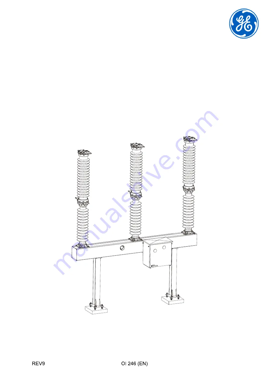
High Voltage Circuit Breaker
GL 310 F1/4031 P/VR GL310 F1/4040 P/VR
GL 311 F1/4031 P/VR GL311 F1/4040 P/VR
GL 312 F1/4031 P/VR GL312 F1/4040 P/VR
GL 313 F1/4031 P/VR
Manufacturer: GE Grid GmbH
Lilienthalstrasse 150 - 34123 Kassel, Germany
B
A
-P
-S
C
H
A
L
T
E
R
-T
IT
E
L
Summary of Contents for GL 310 F1/4031 P/VR
Page 2: ......
Page 8: ...INTRODUCTION 8 REV6 Copyright Notice Trademark Notices...
Page 9: ...INTRODUCTION REV6 9...
Page 10: ...INTRODUCTION 10 REV6...
Page 11: ...SAFETY REV3 11 2 Safety 2 1 Safety Instructions DANGER WARNING CAUTION CAUTION...
Page 12: ...SAFETY 12 REV3...
Page 14: ...HANDLING SULFUR HEXAFLUORIDE 14 REV3 3 1 3 Frostbite WARNING...
Page 15: ...HANDLING SULFUR HEXAFLUORIDE REV3 15 3 2 Safety Precautions When Handling Used SF6 WARNING...
Page 17: ...COMPONENTS SUPPLIED REV1 17 4 Components Supplied 4 1 Scope of Supply Standard...
Page 18: ...COMPONENTS SUPPLIED 18 REV1 4 2 Scope of Supply Optional...
Page 20: ...TRANSPORT AND STORAGE 20 REV1 5 2 Storage CAUTION...
Page 30: ...INSTALLATION 30 REV6 6 4 3 Operating Mechanism 2 T116 3 1...
Page 31: ...INSTALLATION REV6 31 6 5 Preinstalling the Supports...
Page 32: ...INSTALLATION 32 REV6 6 6 Installing the Base Frame see Preinstalling the Supports on Page 31...
Page 33: ...INSTALLATION REV6 33 6 7 Installing the Mechanism Brackets...
Page 35: ...INSTALLATION REV6 35...
Page 36: ...INSTALLATION 36 REV6...
Page 38: ...INSTALLATION 38 REV6 6 9 2 Positioning the Pole Columns...
Page 39: ...INSTALLATION REV6 39...
Page 40: ...INSTALLATION 40 REV6 6 10 Aligning and Connecting the Pole Columns...
Page 42: ...INSTALLATION 42 REV6 6 11 1 Connecting the Drive Rod to the Drive Lever...
Page 43: ...INSTALLATION REV6 43 6 11 2 Connecting the Drive Rod to Pole B...
Page 44: ...INSTALLATION 44 REV6...
Page 45: ...INSTALLATION REV6 45 6 11 3 Connecting the Lever to the Connecting Rod for Pole C...
Page 46: ...INSTALLATION 46 REV6 6 11 4 Aligning and Connecting Pole Column A...
Page 47: ...INSTALLATION REV6 47 6 11 5 Aligning and Connecting Pole Column C...
Page 48: ...INSTALLATION 48 REV6 6 12 Mounting the High Voltage Terminal Pads...
Page 50: ...INSTALLATION 50 REV6 6 14 Earthing Grounding the Circuit Breaker...
Page 53: ...COMMISSIONING REV7 53 Instruction D...
Page 56: ...COMMISSIONING 56 REV7 7 3 Filling the Breaker with Gas CAUTION t C p_rel bar...
Page 57: ...COMMISSIONING REV7 57 t C p_rel bar...
Page 62: ...COMMISSIONING 62 REV7 7 6 6 Manually Charging the Closing Spring...
Page 64: ...COMMISSIONING 64 REV7...
Page 68: ...TROUBLESHOOTING 68 REV2 8 2 3 Replacing the Operations Counter...
Page 69: ...TROUBLESHOOTING REV2 69 8 2 4 Replacing the Motor Limit Switch and or the Auxiliary Switch...
Page 70: ...TROUBLESHOOTING 70 REV2 Motor limit switch Auxiliary switch CAUTION...
Page 72: ...TROUBLESHOOTING 72 REV2...
Page 74: ...TROUBLESHOOTING 74 REV2...
Page 76: ...INSPECTION AND MAINTENANCE 76 REV3 CAUTION 40 2500 3 15 15 n I kA...
Page 80: ...INSPECTION AND MAINTENANCE 80 REV3...
Page 83: ...RECONDITIONING REV7 83...
Page 84: ...RECONDITIONING 84 REV7 10 1 2 Removing the Double Motion System...
Page 86: ...RECONDITIONING 86 REV7 10 1 3 2 Switchgear with 4040 5 6 7 8 21 80 81...
Page 92: ...RECONDITIONING 92 REV7 10 1 9 2 Switchgear with 4040 5 6 7 8 21 80 82...
Page 93: ...RECONDITIONING REV7 93 10 1 10 Reconditioning the Holder...
Page 95: ...RECONDITIONING REV7 95...
Page 98: ...RECONDITIONING 98 REV7...
Page 99: ...RECONDITIONING REV7 99 10 1 14 Replacing the Adsorption filter...
Page 102: ...RECONDITIONING 102 REV7 10 2 2 Disassembling the Crankcase...
Page 104: ...RECONDITIONING 104 REV7...
Page 106: ...END OF LIFE MANAGEMENT 106 REV2a...
Page 108: ...SPECIAL EQUIPMENT OPTIONAL 108 REV0 12 1 1 Functional description Element Description...
Page 109: ...SPECIAL EQUIPMENT OPTIONAL REV0 109 12 1 2 Operating condition H A VHS PL DR R A...
Page 110: ...SPECIAL EQUIPMENT OPTIONAL 110 REV0 12 1 3 Test condition H Z...
Page 115: ...SPECIAL EQUIPMENT OPTIONAL REV0 115...
Page 116: ...SPECIAL EQUIPMENT OPTIONAL 116 REV0...
Page 118: ...DESCRIPTION OF THE EQUIPMENT 118 REV1...
Page 121: ...TOOLS AND AUXILIARY EQUIPMENT REV8 121 Tool Description Illustration...
Page 122: ...TOOLS AND AUXILIARY EQUIPMENT 122 REV8 Tool Combinations Tool Illustration Comment...
Page 130: ...REPLACEMENT PARTS AND ACCESSORIES 130 REV5...
Page 132: ...HANDLING USED SULFUR HEXAFLUORIDE 132 REV2...
Page 134: ...TECHNICAL DESCRIPTION 134 REV0 A5 2 Technical Data Circuit Breaker Type GL 312 GL 313...
Page 135: ...TECHNICAL DESCRIPTION REV0 135 A5 3 Technical Data Spring Operating Mechanism...
Page 136: ...TECHNICAL DESCRIPTION 136 REV0...
Page 141: ...SLOW OPERATION FOR MAINTENANCE PURPOSES REV3 141 150 If Then...
Page 142: ...SLOW OPERATION FOR MAINTENANCE PURPOSES 142 REV3 Locking the Undervoltage Releases If Then...
Page 148: ...SLOW OPERATION FOR MAINTENANCE PURPOSES 148 REV3 Loosening the Manual Release Locking Device...
Page 149: ...SLOW OPERATION FOR MAINTENANCE PURPOSES REV3 149 150 Opening Manually...
Page 151: ......


