30" GAS COOKTOP WITH SEALED
(SPILL-PROOF) BURNERS
DISCONNECT POWER BEFORE SERVICING
IMPORTANT: Reconnect all grounding devices. All parts
of this appliance capable of conducting electrical current
are grounded. If grounding wires, screws, straps, slips,
nuts or washers used to complete a path to ground are
removed for service, they must be returned to their
original position and properly fastened.
229C4059P486
GAS SUPPLY SHUT-OFF VALVE
Certain models of the cooktop are equipped with a gas shut-off valve.
This valve may be turned to the off position by rotating the shut-off
valve knob, mounted in the control panel of the maintop. This shut-off
valve is
NOT
meant to replace the main cooktop shut-off valve
mounted downstream of the gas regulator.
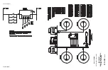
IGNITION SYSTEM
The Ignition System consists of 4 spark switches (1 on each valve),
4 spark electrodes (1 on each burner) and a spark module. The
burner control knob must be turned to the LITE position to light the
burner and out of the LITE position to stop the sparking after the
burner has ignited. All 4 electrodes will spark when any burner control
knob is in the LITE position.
SPARK MODULE ACCESS
Access to the spark module varies depending upon the model
number of the product. Please check the name and number plate
to identify the model number prior to any disassembly.
•
Make sure that power is disconnected before servicing.
•
Remove all control knobs.
•
Remove all burner caps.
LOW FLAME (SIMMER) ADJUSTMENTS (cont.)
Testing flame stability:
Test 1 –
Turn the knob from “HI” to “LOW” quickly. If the “LOW”
flame goes out, increase the flame size and test again.
Test 2 –
With the burner on the “LOW” setting, open and close the
cabinet door under the cooktop. If the flame is extinguished by the air
currents created by the door movement, increase the flame height
and test again.
Flame recheck:
After the adjustment is made, turn all burners off. Ignite each burner
individually. Observe the flame at the “HI” position. Rotate the valve
to the “LO” position and be sure that the flame size decreases as the
valve is rotated counterclockwise.
FOAM GASKET ON BURNER BOX
(Non-Glass Models only)
There is a foam gasket (seal) between the cooktop and the burner box.
This gasket must stay in place to ensure proper airflow to the burners.
CONVERSION TO L.P./PROPANE GAS
The cooktop is shipped with a convertible regulator and a set of
L.P/Propane gas orifices.
1. CONVERT THE REGULATOR:
Remove the spring retainer cap
from the regulator body. Remove the plastic spring retainer from
the center of the cap. Turn plastic spring retainer upside down and
re-install in cap.
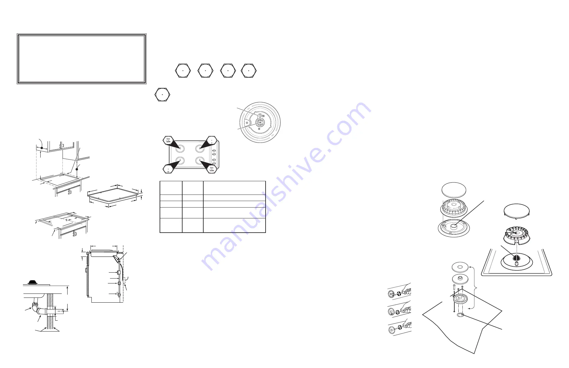
2. INSTALL THE L.P./PROPANE ORIFICES:
Remove the electrode
from the burner base. Remove the burner base using a No. 15 torx
type bit. Using a 7mm nut driver, remove the natural gas orifice
from each burner. Install the L.P./Propane orifices supplied with
the cooktop.*
Note: The 18,000 BTU burner has two orifices,
one main orifice and one simmer orifice. Both must be
replaced in converting to LP/propane gas.
IMPORTANT:
Save the orifices removed from the appliance for
future use. To convert back to natural gas, reverse the previous
steps. Use the Burner/Orifice specification chart to determine proper
location of the orifices.
LOW FLAME (SIMMER) ADJUSTMENTS
To adjust the simmer setting on all burners, except models that have
an 18,000 BTU right front burner, perform the following:
The top burner valves have low flame adjustment screws in the
control valve body. A flashlight may be required to locate the screw.
A thin, flat blade (approximately 3/32" across) screwdriver is needed
to access the screw.
To adjust the simmer setting on the burner:
•
Light 2 other burners and set the knob
to a Medium to Hi setting.
•
Light the burner to be adjusted and
turn the knob to “LOW”.
•
Remove knob.
•
Insert screwdriver through access hole in the
valve switch. Engage adjustment screw in valve.
•
Turn the adjustment screw until the
flame reaches the desired size.
•
Perform a flame stability test.
•
For the right front burner, if 18,000 BTU, the simmer screw is accessed
through the burner valve shaft. Use a small flat-head screwdriver
(4mm or 5/32" tip size, 60mm long) to make the necessary adjustments.
CAUTION
1.
When replacing burner bases on glass top models, do not tighten
screws beyond 10 in. lbs. torque.
2.
When replacing the burner base on the 18,000 BTU burner,
make sure you do not tighten the base too tightly to the burner
inlet. Over tightening will cause stripping of the screw.
3. Cooktops:
Before removing glass maintop, inspect the installation
from below to be sure cooktop is resting on the burner box top
mounting flange and
not
the glass maintop.
4.
The rubber seal must be re-installed to prevent spillovers from
seeping into the burner box bottom.
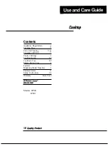
3 3/4" MIN.
clearance from
cutout to side
wall on the left
of the unit
30" MIN.
clearance from
countertop to
unprotected
overhead surface
6" MIN.
clearance from
cutout to side
wall on the right
of the unit
13" MAX. Depth
of unprotected
overhead cabinets
18" MIN.
height from
countertop to
nearest cabinet on
either side of unit
19 5/8"
3" Min.
Electrical
Cord
34" Long
Electrical
Outlet
12" Below
Countertop
Pressure
Regulator
1/2" Pipe
Coupling
Shut Off
Valve
IMPORTANT SAFETY NOTICE: This information is
intended for use by persons possessing adequate
backgrounds of electrical, electronic and mechanical
experience. Any attempt to repair a major appliance
may result in personal injury and property damage.
The manufacturer or seller cannot be responsible
for the interpretation of this information, nor can it
assume any liability in connection with its use.
COOKTOP
30"
21"
19 3/8"
28 1/4"
3"
90
°
STREET EL
45
°
ELBOW
CABINET SIDES
2" DIA. HOLE (20 7/8"
FROM FRONT OF
COUNTERTOP TO
HOLE CENTER)
5" TO CENTER
OF 2" DIA. HOLE
FROM COUNTERTOP
2 1/4" Min.
Between cutout
and the wall behind
the cooktop
19 5/8" width of cut
28 1/2"
length of
cut
2 1/2" Min.
from front edge
of cutout
and front edge
of countertop
14 1/4"
SPARK MODULE ACCESS (cont.)
For all cooktops with glass maintop:
•
Remove the screws securing the burner bases. Use a number 15
torx bit for this removal.
•
Lift the burner bases up from the glass maintop and remove the
spark ignition wire from each burner electrode.
•
Lift the cooktop from the burner box bottom. The spark module is
mounted in the burner box bottom.
For cooktops with 18,000 BTU right front burner:
•
Remove right rear, left front and left rear burner bases by lifting
from maintop.
•
Pull burner electrode up from maintop and remove spark ignition wire.
•
Remove three screws (from each burner) that hold the maintop to
the burner spider. A number 15 torx bit is required.
•
Remove burner head from right front burner by pulling straight up
from burner base. (
Note:
this is a snug fit, so pull straight up).
•
Remove two screws that secure the burner base to the burner inlet.
•
Remove the burner base from the maintop. The maintop may now
be removed, exposing the spark module.
For cooktops with 12,000 or 9,500 BTU right front burner:
•
Remove the burner bases by lifting from maintop.
•
Pull burner electrode up from maintop and remove spark ignition wire.
•
Remove three screws (from each burner) that hold the maintop to
the burner spider. A number 15 torx bit is required.
•
Remove the maintop, exposing the spark module.
CHANGING COOKTOP BURNER ORIFICES
Locate the L.P./Propane orifices. Remove the orifices from the
bracket. The L.P./Propane orifices are shipped in the literature
package. They will have a digit number and the letter “L” on one side.
(Important: Save the orifices removed from the appliance for
future use.)
Each orifice will also show a series of engraved marks, (I, II, III, X, or
none), located on the top. These marks denote the precise location of
each orifice to the cooktop burner.
ORIFICE SPUD
LOCATED THRU
THIS OPENING
ORIFICE SPUD
LOCATED THRU
THIS OPENING
ORIFICE SPUD
LOCATED THRU
THIS OPENING
Cap
Head
Base
Cap
Head
Base
Cap
Head
Base
Remove
This
Assembly
Model
JGP328
II
II
JGP330
II
III
JGP933
III
X
JGP940
JGP945
III
Replace:
With:
Main
206X N
➔
108X L
Simmer
57N
➔
34L
Left Rear
Orifice
Right Front
Orifice
I
II
III
X
The 18,000 BTU/HR burner has 2 orifices with
markings located on the side only. (See rating plate
on bottom of cooktop.)
18,000 BTU/HR BURNER
(on some models)
NOTE:
The main orifice is located
low in the center of the burner while
the simmer orifice is located higher
behind the center of the burner.
Main
Orifice
Simmer
Orifice
21" (21-1/2" Max.
for Glass-Top
Models)