
05-6301A01, Rev. 01
MDS Mercury Series Quick Start
1
MDS Mercury Series
Setup Guide
MDS Mercury
TM
Series transceivers provide an easy-to-install
wireless network service with long range and secure operation at
adaptive data rates approaching 30 Mbps. The transceiver is
designed for demanding applications in industrial environments,
where reliability and range are paramount.
The transceiver comes in two primary models—
Base Station (BS)
and
Subscriber Unit (SU)
, each with unique hardware profiles.
Both models support Ethernet and serial services. A BS is a wire-
less switch that usually provides connectivity into a wired Ethernet
LAN/WAN.
Subscriber Units associate over the air with a BS and are typically
connected to an Ethernet or Serial device via a local cable. The
outward appearance of the standard SU is very similar to the BS.
NOTE:
To determine whether a unit is an BS or Subscriber Unit,
check the dome label on the top of the unit.
Refer to the Mercury Series Technical Manual (05-6302A01) for
advanced procedures and additional information.
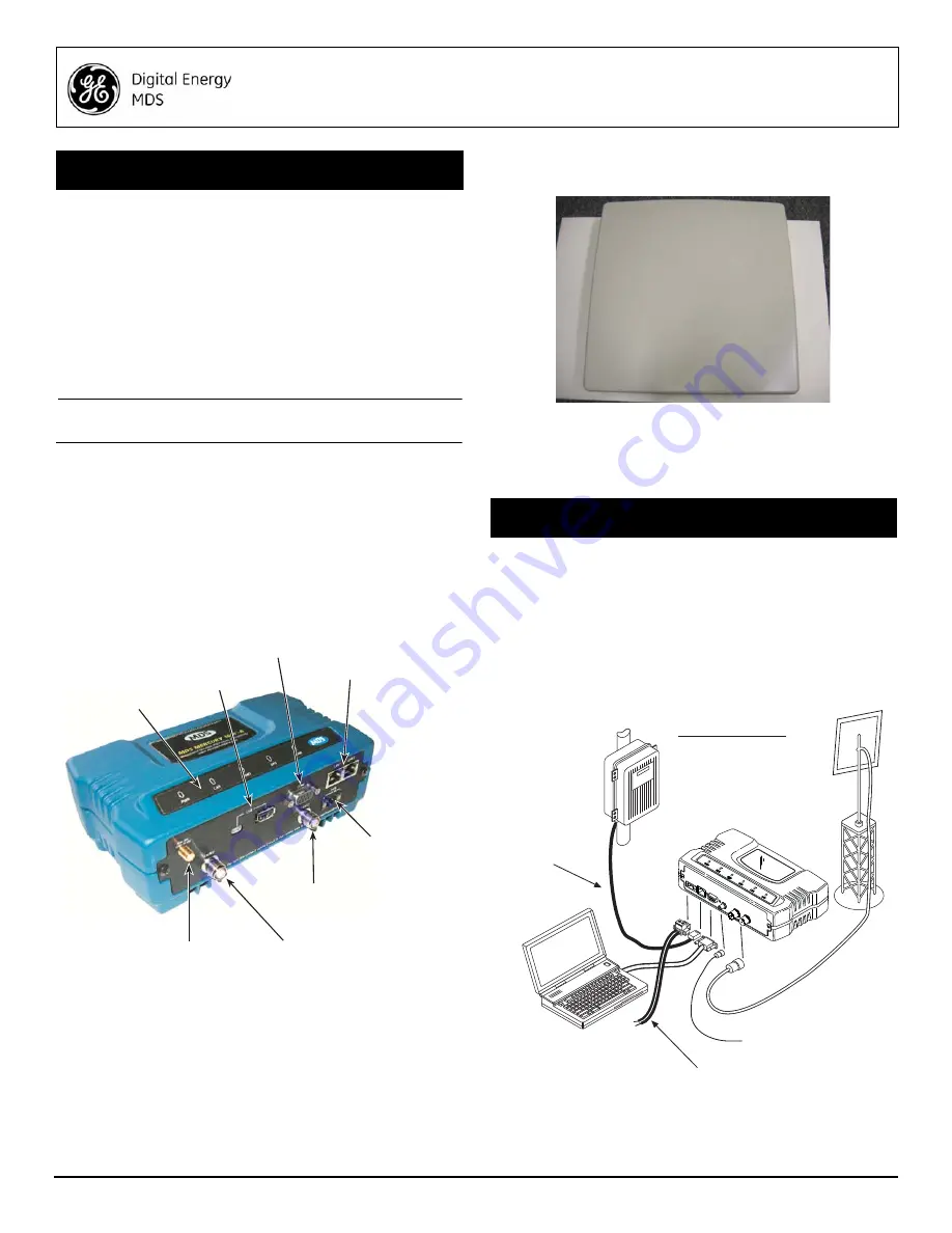
1.1
Connectors & Indicators
Figure 1
shows the connectors and indicators of a Standard BS.
These items are referenced in the installation and operation steps
that follow. Note that SU radios may have an additional connector
present for Wi-Fi service, depending on order requirements. If
Wi-Fi is
not
provided on an SU, the GPS connector will also be
absent.
Invisible
place
holder
Figure 1. Connectors and Indicators
(Standard BS shown; SU Similar)
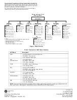
1.2
Weatherproof Subscriber Unit
In addition to the Standard Subscriber Unit, a weatherproof Out-
door Unit (ODU) model is offered (see
Figure 2
). The ODU is
designed for mounting on a tower, pole, or other elevated struc-
ture, and includes an integral panel antenna.
DC power is typically applied to the ODU through a Category 5
Ethernet cable (Cat. 5E, Cat. 6 also acceptable) which provides
Power-over-Ethernet (PoE) service. The cable can be up to 100
meters in length (328 feet). For non-PoE models, a separate DC
power cable is required to supply 10-65 Vdc.
Invisible
place
holder
Figure 2. Mercury ODU Subscriber Unit
All operating parameters and commands for the ODU are identical
to those of the indoor SU. The only difference is in the physical
installation of the hardware on its support structure.
There are three main requirements for installing all units in the
transceiver system—adequate and stable primary power, a good
antenna system, and the correct interface between the transceiver
and the data device.
Figure 3
shows a typical Mercury installation.
2.1
Installation Steps
Listed below are the basic steps for installation. It is highly recom-
mended that the BS be installed
first
so that
you can quickly check
the operation of each associated SU as it is placed on the air.
Invisible
place
holder
Figure 3. Typical Mercury Installation (SU Shown; BS Similar)
1.0
INTRODUCTION
DC INPUT
(1060 VDC, 4A MAX)
RS-232
SERIAL PORT
LAN PORTS
USB PORTS
(Mini-A, Type-A)
GPS ANTENNA
CONNECTION
WiMAX RF
CHANNEL 1
WiMAX RF
CHANNEL 2
LED INDICATOR
PANEL
2.0
INSTALLATION—ALL UNITS
TO DC POWER SUPPLY
(1060 Vdc)
RTU/PLC
LOW
-LOSS FEEDLINE
(To S
tation
Antenna)
PC RUNNING
TERMINAL
PROGRAM
(Straight-Through
Cable to Radio)
TO GPS ANTENNA
(Provides 3.3 Vdc output)
Crossover Cable
to Radio
ANTENNA SYSTEM
Subscriber: Panel Ant.
Base Unit: Sector Ant.


