GE Infrastructure Water and Process Technologies
Merlin™
Point of Use
Drinking Water System
Installation and Maintenance Manual
Page 1: ...GE Infrastructure Water and Process Technologies Merlin Point of Use Drinking Water System Installation and Maintenance Manual...
Page 2: ...ing dealer every six months See the back cover of this manual for the installing dealer s contact information Consult your local public works department for plumbing and sanitation codes Follow your l...
Page 3: ...RO membrane elements BEFORE INSTALLING THE RO SYSTEM Best performance of the system will be achieved when the incoming water has been treated softened The water coming into the system must be within c...
Page 4: ...Stream 1240116 1 Disconnect Elbow and O ring Permeate Stream 1240118 5 3 8 inch Collet Lock Clip 1240627 3 White Sumps 1239705 3 Sump O ring 1240326 2 Lubricant Silicone 1013501 1 3 8 inch Tube To Thr...
Page 5: ...uld be placed near the sink where drinking water is normally obtained Convenience of use filling of water pitchers and glasses and an open area beneath the faucet under the sink for attaching product...
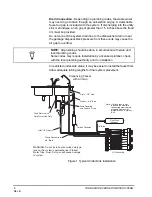
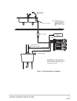
Page 6: ...ing lengths for final system placement Figure 1 Typical Under Sink Installation NOTE All plumbing should be done in accordance with state and local plumbing codes Some codes may require installation b...
Page 7: ...al Drain 3 8 Black Feed Water Valve Cold Water Line Only 1 4 Blue Carbon Postfilter Product 3 8 Blue RO Assembly Note If a flush tank is not installed the manifold connection must remain plugged Remov...
Page 8: ...assembly STEP 6 Put system into operation STEP 1 INSTALL COLD WATER SUPPLY VALVE Comply with local plumbing codes A typical connection using a water supply valve is shown The feed water valve is not i...
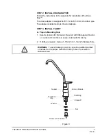
Page 9: ...LL FAUCET A Prepare Mounting Hole 1 Select a location for the faucet Be sure it will fit flat against the sink or counter and that there is space underneath for tubing 2 If drilling is needed make a 1...
Page 10: ...using the air gap module push the black 3 8 inch tubing onto the small hose barb from the collar The red 1 2 inch tubing is pushed onto the large hose barb 8 Put the faucet into position 9 The horsesh...
Page 11: ...f the faucet is not using the air gap module When the tubing is in position use the supplied hose clamps to secure the connection NOTE Make sure the tubing is pushed past the O rings for a secure fit...
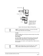
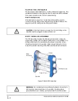
Page 12: ...RO Assembly includes the following components sumps 3 support leg prefilter RO membrane elements 2 and postfilter The tubing is attached to the manifold by the elbow connectors When choosing a locatio...
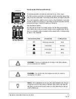
Page 13: ...fitting connections Each fitting has a unique keyed socket on the manifold Each fitting also has a graphic symbol molded into the elbow with a corresponding symbol on the manifold Connector Symbol Con...
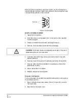
Page 14: ...e elements from packaging 5 Lubricate element O rings brine seals and sump O rings with silicone lubricant 6 Securely insert O ring end of membrane elements into manifold 7 Remove carbon sediment pref...
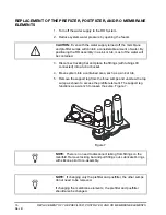
Page 15: ...be replaced every six to twelve months Whenever the prefilter is replaced the postfilter should also be replaced REPLACEMENT OF RO MEMBRANE ELEMENTS The functional life of the RO membrane elements wil...
Page 16: ...shown to access the prefilter element The support leg functions as a wrench to loosen the sump Figure 7 Figure 7 CAUTION Even with the water supply turned off the membrane and prefilter sumps will con...
Page 17: ...o manifold See Figure 8 E Replace sumps and hand tighten 8 Sanitize the system A The manifold should be positioned flat with the sump connections facing up Figure 8 CAUTION The person handling the fil...
Page 18: ...g back approximately 1 4 inch prior to connecting the new postfilter Make sure flow direction arrow aligns with water path Reinsert tubing and collect locks 11 Re connect the fittings to the manifold...
Page 19: ...for any system leaks The RO system is now ready for use NOTE If the two RO membrane elements were replaced the system should be flushed for one hour This flush removes the food grade preservative from...
Page 20: ...20 APPENDIX Rev B APPENDIX...
Page 21: ...NG 3 8 B L UE T UB ING 1 2 NAT UR AL T UB ING 1 2 R E D T UB ING L OC K ING B AR DIS C ONNE C T P N 1239731 C OL L E T L OC K C L IP R E D P N 1240626 1 C OL L E T L OC K C L IP W HIT E P N 1240627 5...
Page 22: ...Tubing 500 foot roll John Guest Brand 1240622 1 2 inch Natural clear 250 foot roll John Guest Brand 1240623 1 2 inch Red Tubing 250 foot roll John Guest Brand 1240117 1 2 inch Feed Disconnect Elbow Wh...
Page 23: ...Feed Valve Tee 14 mm x 14 mm x 1 2 OD Tubing SeaTech 1262406 Feed Valve Tee 15 mm x 15 mm x 1 2 OD Tubing SeaTech 1262407 Feed Valve Tee 3 8 x 3 8 threaded x 1 2 Tubing SeaTech 1262408 Feed Valve Tee...
Page 24: ...Temperature 40 F 4 44 C 100 F 37 78 C Inlet TDS 50 mg L 2 000 mg L Inlet Hardness 0 mg L 0 grain 171 mg L 10 grain Inlet Chlorine 0 mg L 1 0 mg L Inlet Iron 0 mg L 0 1 mg L Inlet Manganese 0 mg L 0 05...
Page 25: ...DIMENSIONS 25 Rev B...
Page 26: ...tion of the Merlin system performance data sheet 0 049 0 00265 0 00612 94 6 Barium 11 1 0 189 1 9 98 3 Cadmium 0 0307 0 0000704 0 0000704 99 8 Chromium VI 0 353 0 00742 0 0147 97 9 Chromium III 0 312...
Page 27: ...imum Operating Conditions Actual system performance will vary depending on varying water temperature and pressure TDS levels and inlet water chemistry Operating the system in water conditions outside...
Page 28: ...Copyright 2004 General Electric Company Printed in the USA P N 1262366 Rev B Contact your installing dealer for spare parts or service...