background image

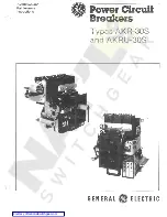
Installation 
Manual 

G EK-64468 

• 

MicroVersaTri

Conversion Kits 

Breaker Types 

AK/AKU/AKT-50, 

AKS/ AKSU/ AKST -50, 

AK/AKR-75, AK/AKR-100 

GENERAL 

fl 

ELECTRIC 

www 

. ElectricalPartManuals 

. com 

Summary of Contents for MicroVersaTrip AK-100

Page 1: ...Installation Manual GEK 64468 MicroVersaTriP Conversion Kits Breaker Types AK AKU AKT 50 AKS AKSU AKST 50 AK AKR 75 AK AKR 100 GENERAL fl ELECTRIC w w w E l e c t r i c a l P a r t M a n u a l s c o m ...

Page 2: ... 4 2 Breaker Conversion AK AKS 50 Drawout 13 4 3 Breaker Conversion AK AKS 50 Stationary 14 4 4 Breaker Conversion AK AKS 75 100 Drawout 14 4 5 Breaker Conversion AKR 75 100 Stationary 15 4 6 Equipment Conversion 15 4 7 Neutral Sensors 19 SECTION 5 Programmer Installation 23 5 1 General Information 23 5 2 AK AKS 50 Installation 2 3 5 3 AK AKR 75 100 Installation 2 3 SECTION 6 Testing and Troublesh...

Page 3: ...th Wire 4th Wire Ground Ground Ground Ground Fault Fault Fault Fault AK 50 AKT 50 4 5 6 5 AKU 50 AKS 50 AKST 50 1 1 1 2 1 3 1 2 AKSU 50 AK 75 7 8 N A N A AK 1 00 9 1 0 N A N A AKR 75 23 24 25 24 AKR 1 00 1 7 1 8 1 9 1 8 AKR W 1 00 20 21 22 21 N A Not Available installing the kit on the breaker an associated neutral sensor CT is required for separate mounting in the equipment Insure also that retro...

Page 4: ...me Adj short time delay Short time Ft switch Instantaneous Adj instantaneous pickup X Adj ground fau lt pickup 1 ph 2 w 3 ph 3 w 3 ph 4 w Ground Fault Ground retu rn Adj ground fault delay Trip indication targets Overload short circuit Other Functions local only 0 L S C and ground fault local only No suffix is required for standard Req uires short time function Table 1 6 Related Publications Break...

Page 5: ...d X Relays Type AK 2 2A Breakers EC trip devices electrically operated with quick close may require the relocation of their anti pump W Relay to insure proper space for the MicroVersaTriprM programmer unit On these breakers the W Relay normally mounts on the left side of the center channel sharing a common mounting bracket with the X Relay as shown in Fig 2 1 Remove the W relay and using the new m...

Page 6: ...sensor systems the flux shifter mounting holes must be added to the left side of the front frame The drill pattern for the required three 3 0 209 diameter holes is given in Fig 2 5 Install the flux shifter as described in Section 2 4 Step 3 and as shown in Fig 2 4 6 NOTE If the breaker is an AKU 50 fused type take care to position the Flux Shift Trip device suffi ciently upward to avoid interferen...

Page 7: ... shown in Fig 2 6 TRIP PADDLE IN MECHANISM RESET POSITION SIDE LINK CROSSBAR BREAKER OPEN TRIP ROD IN RESET POSITION ADJUSTER END Fig 2 6 Flux shifter adjustments 2 4 2 Adjustments Once the flux shifter and its trip paddle are installed and the breaker frames are reassembled the following adjustments must be made 1 With the mechanism in the RESET position set the gap between the trip paddle and th...

Page 8: ... in Fig 2 8 Once the plate is installed assemble the mounting bracket to the plate using the holes closest to the front of the breaker See Fig 2 7 2 6 Programtner Harness Installation The programmer harness consists of the mating 36 pin pro grammer connector and the 16 pin front frame half of the front back frame connector Insert 36 pin programmer con nectors beveled edges on the right hand side f...

Page 9: ...bracket See Fig 2 3 The actuator bracket must be assem bled to the left side link of the left pole as shown in Fig 3 1 If the actuator bracket mounting holes are not in the left side link the holes must be added Drill and tap two 2 five sixteenths 511s of an inch x 18 inch holes using the hole pattern given in Fig 3 2 Fig 3 1 Flux shifter actuator bracket installation LEFT HAND LINK LEFT HAND POLE...

Page 10: ...g 3 3 Lower adapter connector Fig 3 4 MicroVersaTrip phase sensors and harness installed AK AKS 50 3 4 Phase Sensors AKR 75 100 For SST and ECS equipped breakers 1 Remove the back frame harness from the sensor terminal boards 2 Remove the primary finger disconnect assemblies from AKD 6 or Substructure breakers Z long bolts 3 Remove the locking ring and slide off the phase sensor 4 Remove the senso...

Page 11: ...ack frame as shown in Fig 3 8 using the hardware provided 4 Form each sensor s leads downward between the pole bases and thru the hole in its terminal board as shown in Fig 3 8 Wire tie and solder to the terminals as indicated Be sure to position wire colors as shown For SST equipped breakers The MicroVersaTriprM sensor is physically identical to the SST sensor Follow the basic procedure given abo...

Page 12: ...lll MOUNTING WHEN USED THE 4TH WIRE NEUTRAL SENSOR DISCONNECT BLOCK MOUNTS ON TOP OF TAP TERMINAL BOARD VIA ITS TWO LOWER MOUNTING SCREWS THE AKD 5 TYPE MOUNTING IS ILLUSTRATED THE ARRANGE MENT FOR AKD TYPES IS IDENTICAL EXCEPT FOR USE OF A DIFFERENT MOUNTING BRACKET SEE FIG 4 3 HOUSING Fig 3 8 Typical AK 75 100 brackframe conversion rear view w w w E l e c t r i c a l P a r t M a n u a l s c o m ...

Page 13: ...4th wire neutral disconnect 0 38 DIAMETER HOLE REAR VIEW DIMENSIONS IN INCHES 4 2 Breaker Conversion AK AKS 50 Drawout The 4th wire disconnect for the AK AKS 50 Drawout breaker mounts to the lower back frame as shown in Fig 4 1 1 If the disconnect is existing just replace the control harness Maintain the following color code WHITE COMMON BLACK TAP 2 If the disconnect is being added mount the disco...

Page 14: ...UNTING HARDWARE DRILL 2 0 219 DIAMETER HOLES 4 4 Breaker Conversion AK AKR 75 100 Drawout There are two 4th wire disconnect designs used with these breakers One design is used on breakers for AKD Type equipment The other design is used on breakers for AKD 5 6 Type equipment The difference in the designs is the bracket used for mounting the disconnect to the breaker Figure 4 3 depicts thetwo design...

Page 15: ... Stationary The 4th wire disconnect for stationary AKR 75 100 breakers is similar to the terminal board used by the AKS 50 breakers See Section 4 3 for details 4 6 Equipment Conversion The equipment compartment contains the mating portion of the 4th wire disconnect and the neutral sensor The neutral sensor is discussed in Section 4 7 The AKD AKD 5 6 and Substructure Type equipment com partments us...

Page 16: ...6 I I LEFT POLE I OF BRACKET k DRILL 2 0 218DIAMETER HOLESIN COMPARTMENT 3 75 1 2 _l_ COMPARTMENT I 14 8 62 1 SIDE VIEW OF COMPARTMENT VIEW LOOKING AT REAR OF COMPARTMENT DIMENSIONS IN INCHES 225 Breaker portion of 4th wire disconnect 235 20 flat washer 226 Equipment portion of 4th wire disconnect 236 1 20 lock washer 230 10 32 x 1 375 inch mounting screws 237 1 20 nut 231 Insulation 238 1 20 x 1 ...

Page 17: ... wire disconnect installation AKD 5 type REAROF BREAKER 1 PHASE SENSOR TERMINALBOARD REAROF COMPARTMENT CENTER LEFT POLE POLE 7 00 J 1BRACKET i l HOLESIN 228 COMPARTMENT 11 DRILL 2 0 281 DIAMETER r SIDE VIEW OF COMPARTMENT DIMENSIONS IN INCHES 225 Breaker portion of 4th wire disconnect 226 Equipment portion of 4th wire disconnect 228 Mounting bracket AK 75 for AKD type compartments 230 10 32 x 1 3...

Page 18: ...5 inch mounting screws 239 Bracket Fig 4 8 AK 100 4th wire disconnect installation AKD type PHASE SENSOR TERMINAL BOARD I REAROF I BREAKER _ SIDE VIEW OF COMPARTMENT DIMENSIONS IN INCHES 225 Breaker portion of 4th wire disconnect 226 Equipment portion of 4th wire disconnect 228 Mounting bracket AK 75 for AKD type compartments 230 10 32 x 1 375 inch mounting screws 231 Insulation 232 10 Lock washer...

Page 19: ...lectrical duplicate of the phase sensor including the taps Therefore when taps are changed on the phase sensors the taps on the neutral sensor must be correspondingly positioned Mount the neutral sensor in the outgoing neutral lead nor mally in the equipment s bus or cable compartment Be sure to observe the sensor s LINE and LOAD directional markings See Fig 4 11 and Fig 4 12 for the sensor s bar ...

Page 20: ... I I 1 EFT fi7 DIMENSIONS IN INCHES 0 032 o_j_ SENSOR CAT NO TSVG830BK TSVG940BK Fig 4 11 Outline of the AKR 75 100 and AK 75 100 neutral sensor AMPERES 1200 3000 1600 4000 w w w E l e c t r i c a l P a r t M a n u a l s c o m ...

Page 21: ...620BK 800 2000 A 0 250 0 500 0 625 GEN 0 ELECTRIC OBSERVE LINE ANO LOAD CONNECTIONS BOND OR GROUND ON LINE SIDE ONLY B 3 25 3 62 3 25 c 0 75 0 94 0 75 D 0 562 DIAMETER HOLES MAXIMUM f 1 25 STRAP n E 3 20 1 30 3 20 1 30 3 33 1 1 8 Fig 4 12 Outline of the AK AKS 50 neutral sensor 21 w w w E l e c t r i c a l P a r t M a n u a l s c o m ...

Page 22: ...K IN DRAWOUT BREAKER COMPARTMENT SEE BELOW OR TERMINAL BOARD TB4 ON STATIONARY BREAKERS EQUIPMENT PORTION OF 4TH WIRE DISCONNECT 2 28 TAP COMMON FRONT VIEW LOOKING INTO BREAKER COMPARTMENT TAP 6 PAN HEAD SCREW COMMON 4TH WIRE NEUTRAL SENSOR STATIONARY DISCONNECT BLOCK ON DRAWOUT BREAKERS DIMENSIONS IN INCHES NEUTRAL SENSOR 5 BINDING HEAD SCREW Fig 4 13 Connecting the 4th wire neutral sensor w w w ...

Page 23: ...sh on the programmer This will engage the connectors and release the locking lever which will move upwards 2 Verify that the locking lever actually engaged the programmer pin To remove the programmer 1 Move locking lever to horizontal position thus releasing the programmer pin 2 Remove programmer 5 3 AK AKR 75 100 Installation The AK AKR 75 100 mounting bracket is shown in Fig 2 9 Installation is ...

Page 24: ... curves given in Fig 6 9 and Fig 6 10 B Test the components of the MicroVersaTrip system using portable Test Set Type TVTS1 The applicable test procedures are detailed in Instruction Book GEK 64464 6 3 Troubleshooting When malfunctioning is suspected the first step in trouble shooting is to examine the circuit breaker and its power system for abnormal conditions such as 1 Breaker tripping in prope...

Page 25: ... that the harness connections to the sensors meet the polarity constraints indicated by the cabling diagram q A q B q c AAA BREAKER t t t 1 BACK FRAME 4 On Ground Fault breakers serving four wire loads check that the neutral sensor is properly connected See cabling diagram Fig 6 3 In particular the following A Verify that the neutral sensor has the same rating and tap setting as the phase sensors ...

Page 26: ...d fault on 3 wire load cpA cpB cp i C FLUX SHIFT AA A TRIP DEVICE BREAKER r 4 l BACK FRAME o O O LEFT POLE I CURRENT OM I SENSOR nl _ I NEUTRAL I I I A NEUTRAL I SENSOR DISCONNECT LINE l I 1 I COM1 lc EQUIPMENT MOUNTED NEUTRAL SENSOR 4 WIRE LOAD PROGRAMMER UNIT Fig 6 3 Cabling diagram MicroVersaTrip with ground fault on 4 wire load w w w E l e c t r i c a l P a r t M a n u a l s c o m ...

Page 27: ... I I o I o I I o t I o I o 4 I o 1 I o I I I o I 0 I 0 l L_j GROUND FAULT DEFEAT MODULE PROGRAMMER CAT NO TVTGD9 UNIT r I _ I L I D I f L 4 I a r I l 0 0 0 3 4 5 a r l I f1 o I I I I I I t o I I t O I I ol lol I I 0 I ANY MICROVERSATRIPTM Io I PROGRAMMER UNITWITH I GROUND FAULT I ELEMENT I 4 o I I I L J L __ _j Fig 6 5 Cabling diagram with ground fault defeat module inserted between breaker harnes...

Page 28: ...CTOR PROGRAMMER CONNECTOR Fig 6 6 Partial cable diagram H option winding connections PROGRAMMER SECONDARY DISCONNECT EQUIPMENT BREAKER AMP AMP 1 350239 9 1 350246 9 REMOTE FAULT INDICATION CONNECTOR MICROVERSATRIP lM PROGRAMMER YELLOW I I I YELLOW AMP AMP GREEN I GREEN I BLUE I BLUE I I L______j 1 350242 9 1 350235 9 Fig 6 7 Cabling diagram remote fault indication w w w E l e c t r i c a l P a r t...

Page 29: ...HARNESS CONNECTOR SHORT TIME OUTPUT l r GROUND FAULT j INPUT 1 H Hn r GROUND FAULT OUTPUT 1 r Hn r AMP AMP 1 350239 9 1 350246 9 MICROVERSATRIP PROGRAMMER I I I I I I I I L ___ J Fig 6 8 Cabling diagram zone selective interlock 29 w w w E l e c t r i c a l P a r t M a n u a l s c o m ...

Page 30: ...rvne i I L Application Oetarmineo l V End of Curve X 1 VU II Instantaneous Adiustment P ckup setting 0 4 0 6 0 B 1 0 multiples of breaker short t1me mterruptmg ratmg H XXX Wl 11 4 5 1 7 1 I 1 2 3 4 I I l I 111 MULTIPLES OF BREAKERSHORT TIME RATING t f y Hf j f N iT tr8 N ll 13 Fixed Instantaneous 1 hH t t HOverride D Option f 50160 Hertz _ Operation Onty l hH t t HI i 2 Molded Casa and Insulated C...

Page 31: ...0 101011 LVPCB MC ICCB Max LVPCB V 717 20 fo 1 o r v l II Vv 30 40 50 10 701010 MC ICCB LVPCB MC ICCB I MULTIPLES OF GROUND FAULT PICK UP SETTING I U U Fig 6 10 MicroVersaTrip ground fault time versus current curves 1000 900 100 700 800 500 1 1 1 400 300 200 00 10 70 10 50 40 20 I I 7 I s 3 2 I Ill 1 z _ 07 Ill 04 03 02 31 w w w E l e c t r i c a l P a r t M a n u a l s c o m ...

Page 32: ... purchaser s purposes the matter should be referred to the General Electric Company These instructions are intended for use by qualified personnel only Outs1de the U S and Canada wnte Export Sales and Serv1ces 570 Lex1ngton Avenue New York NY 1 0022 GEK 64468 06 83 PA E For further information call or write your local General Electric Sales Office or General Electric Co Distribution Eq uipment 41 ...

Reviews: