background image


DEH40228 - Installation Instructions


PowerMark Plus

™ Load Centers

100

225 Ampere Single- and Three-Phase 10

42 Circuit 

Indoor Type

WARNING

Hazard of electrical shock or burn. Turn 

off power before working inside this equipment. 


General 

To comply with the Canadian Electrical Code and the 

Canadian Standards Association, the load center must be 

installed in accordance with the information included on 

the label on the inside of the equipment. This must also 

be done in accordance with the applicable local electrical 

codes and by a qualified electrical contractor or licensed 

electrician. 

Installation 
1. Remove Front 

Slip the front and the accessory package back into the 

carton to protect the finish. 

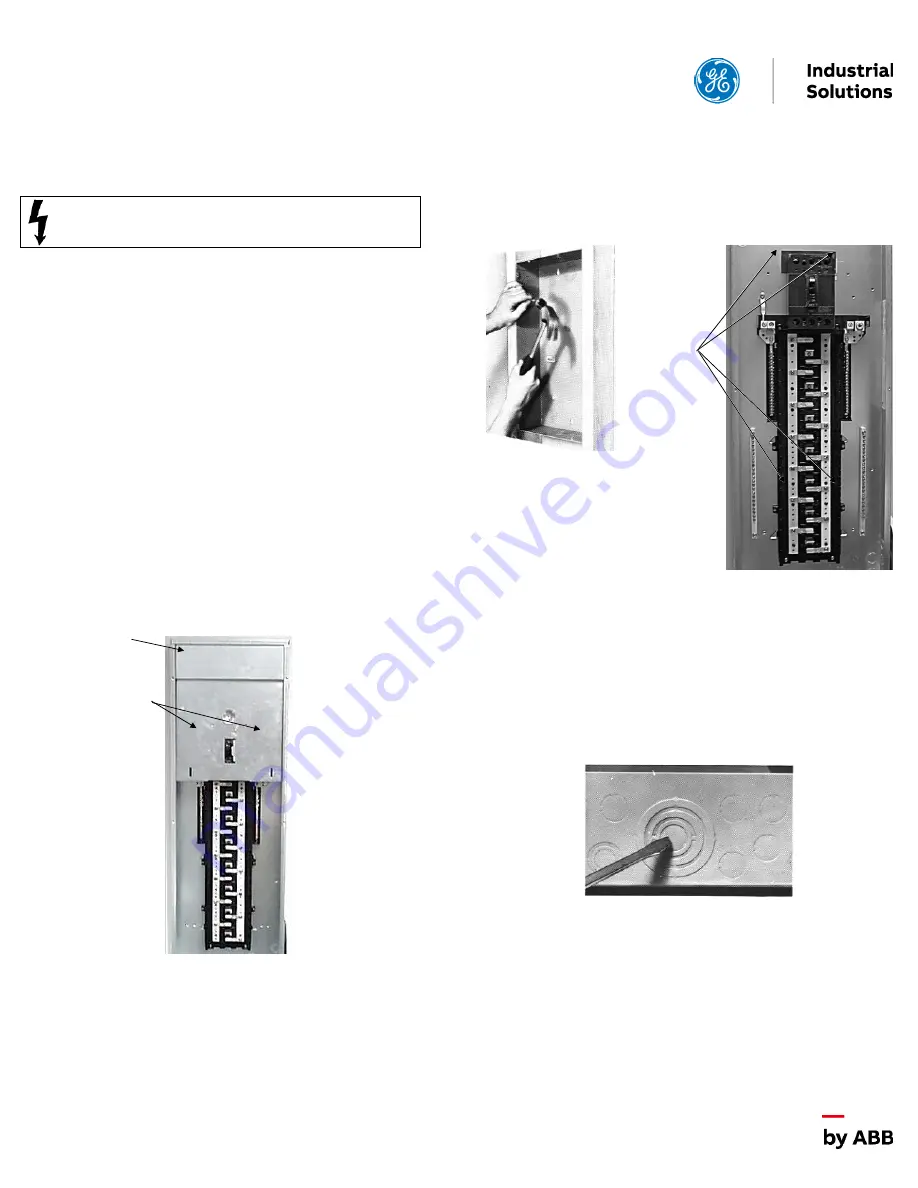
2. Remove Service Entrance Barrier (Main Breaker only) 

Back out and save the two mounting screws securing the 

service entrance barrier over the main breaker 

connections, then lift the barrier up and out. 


3. Remove Interior (Optional) 

Back out the mounting screws and save them for reuse. 


4. Mount Box 
Flush mount:


Line up the front box edge with the finish 

wall  surface  and  screw  or  nail  to  the  stud  through  the 

small knockouts in the box side. 

Surface  mount:


Screw  or  nail  through the keyhole 

slots in the back of the box. 

5. Remove Knockouts for All Main and Branch Circuits 

First knock the center knockout inward. The outer rings 

should be alternately pried up or driven in one at a time. 


6. Pull Incoming Service and Branch Circuit Wiring into 

Box 
7. Replace Interior 

Drive in the mounting screws loosened in step 2. 


Barrier 

Mounting 

Screws 

Mounting 

Screws 

Summary of Contents for PowerMark Plus DEH40228

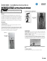
Page 1: ...arton to protect the finish 2 Remove Service Entrance Barrier Main Breaker only Back out and save the two mounting screws securing the service entrance barrier over the main breaker connections then lift the barrier up and out 3 Remove Interior Optional Back out the mounting screws and save them for reuse 4 Mount Box Flush mount Line up the front box edge with the finish wall surface and screw or ...

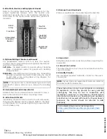
Page 2: ... barrier with the two mounting screws 11 Wire Branch Circuits Individually wire each branch circuit into a circuit breaker then plug the breaker into the interior Refer to the label on the breaker for the proper tightening torque Use GE circuit breakers only 12 Remove Cover Knockouts Place a screwdriver as shown and tap with a hammer 13 Important Retighten all electrical connections before energiz...

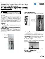
Page 3: ...joncteur principal seulement Dévisser et conserver les deux vis de montage retenant la barrière de l entrée de service par dessus les connexions du disjoncteur principal puis soulever la barrière par en haut et l enlever 3 Enlever l interieur facultatif Retirer les vis de montage et les conserver pour les réutiliser 4 Monter la boîte Montage encastré aligner le côté devant de la boîte avec la surf...

Page 4: ...nstaller la barrière de l entrée de service retirée à l étape 2 Fixer la barrière avec les deux vis de montage 11 Câbler les circuits de dérivation Câbler individuellement chaque circuit de dérivation à un disjoncteur puis le brancher à l intérieur Vous référer à l étiquette sur le disjoncteur pour un couple de serrage approprié N utiliser que des disjoncteurs GE 12 Enlever les débouchures du couv...

Reviews: