background image

GE Healthcare 


T2100-ST1 Treadmill, 110V / T2100-ST2 Treadmill, 

220V 

English 

© 2016-2019 General Electric Company 

All Rights Reserved 


T2100-ST1 

Treadmill, 110V 

T2100-ST2 

Treadmill, 220V 

Service Manual 


2097937-002 Rev G 


Summary of Contents for T2100-ST1

Page 1: ...ealthcare T2100 ST1 Treadmill 110V T2100 ST2 Treadmill 220V English 2016 2019 General Electric Company All Rights Reserved T2100 ST1 Treadmill 110V T2100 ST2 Treadmill 220V Service Manual 2097937 002 Rev G ...

Page 2: ...However the ultimate conformance to IEC 6060 1 2005 3rd edition is the responsibility of the system integrator when combined with other equipment Additionally all motorized equipment is potentially dangerous if used incorrectly Before using the T2100 ST1 or T2100 ST2 treadmill follow all precautions listed in this manual and read the entire operator s manual thoroughly Use the T2100 ST1 and T2100 ...

Page 3: ...mmunity ME Equipment and ME Systems that is NOT Life supporting 16 Table 4 Recommended Separation Distances between portable and mobile RF Communications equipment and the T2100 ST Series ME Equipment and ME Systems that is NOT Life supporting 17 Responsibility of the Manufacturer 17 Responsibility of the Customer 18 Product and Package Information 20 Symbols 20 Equipment Identification 23 Product...

Page 4: ...ng Adjustment 42 Running Belt Tension Adjustment 42 Drive Belt Tension Adjustment 43 Test Plug Procedure 43 Communication Ports 43 Using the test plug 44 Setup and Connection to Host 45 CASE connection and setup 45 CardioSoft CS connection and setup 47 MAC 5500 ST connection and setup 53 MAC 2000 ST connection and setup 54 4 Preventive Maintenance 57 Daily Maintenance 57 Weekly Maintenance 58 Mont...

Page 5: ...oting Guidance Base on Error Code 76 Incoming Power 110 240VAC Flow Chart 1A 78 Incoming Power Inline Filter Flow Chart 1B 79 Incoming Power Drive PC2303 012 N Flow Chart 1C 80 Smart Power Supply Incoming Power 110 240VAC Flow Chart 1D 81 Emergency Stop Flow Chart 1E 82 Pull Tether Flow Chart 1F 83 Communication RS232 Flow Chart 1G 84 Communication USB Flow Chart 1H 85 Smart Power Supply Error Cod...

Page 6: ...Belt High Speed Application 98 System Flash Log Retrieval 98 7 Field Replaceable Units 100 Final Assembly 100 Final Assembly Circuit Board Connection 101 Deck Assembly 104 Frame Assembly 106 Motor Pan Assembly 108 Motor Pan Assembly Wiring 111 Motor Mount Assembly 115 Circuit Board Assembly FGLF0495 1 116 Circuit Board Assembly FGLF0495 3 117 Pull Tether Assembly 119 Emergency Stop Assembly 120 Co...

Page 7: ...ving 154 Replacing the Main power switch 155 Adjusting the Run Belt Tracking and Tension 156 Adjusting belt tracking 156 Adjusting belt tension 157 Replacing the Power cord 157 Replacing the CE filter 158 Replacing the Relay 159 9 Calibration 161 Installing the T2100 ST Series Calibration Software 161 Installing the Serial Drivers 163 Software Interface Instruction T2100 ST Series Calibration 167 ...

Page 8: ...evation Calibration 183 Test Plug Check 183 Walking Belt Tension Tracking 183 Walking Belt Speed Verification 183 Host Communication 184 Electrical Safety Checks 184 Preventative Maintenance Visual Functional Checks 185 Procedural Lists 185 FRU Repairs Exchange 186 Final Checkout Preventative Maintenance Test 188 A Maintenance Log 189 B Reference Documents 191 ...

Page 9: ...ed for service personnel responsible for the maintenance and repair of the T2100 ST1 and T2100 ST2 treadmills Indications for Use The T2100 ST1 and T2100 ST2 treadmills are designed for cardiac stress testing Prescription Device Statement CAUTION United States federal law restricts this device to sale by or on the order of a physician Regulatory and Safety Information This section provides informa...

Page 10: ...actice which if not avoided could result in moderate or minor injury NOTICE Indicates a potential hazard or unsafe practice which if not avoided could result in loss or destruction of property or data Safety Hazards The following messages apply to the system as a whole Specific messages may also appear elsewhere in the manual WARNING The T2100 ST1 and T2100 ST2 treadmills are manufactured to exact...

Page 11: ...mills WARNING Before permitting anyone to use the T2100 ST Series do the following Warn each user about the risk of falling while the belt is in motion Stress the need for caution Demonstrate the proper mounting and dismounting methods Show each user how to use the T2100 ST Series as described in this manual Ask each user to perform a supervised test usage at minimum belt speed to review and pract...

Page 12: ... immediately Never use the treadmill outdoors Immediately discontinue use and unplug the treadmill if you smell the distinctive odor of hot electrical components WARNING Serious injury or death could result from electrical shock occurring during defibrillation Never allow patient or operators near treadmill during defibrillation WARNING Consult your physician prior to using this appliance to deter...

Page 13: ...s of sterilization or disinfection recommended by the manufacturer Not applicable Mode of operation Continuous operation Regulatory and Safety Conformance T2100 ST1 and T2100 ST2 treadmills meet FDA Class 1 motor operated physical medicine machines They have been tested by Intertek Testing Services N A Inc and are listed by Engineering Testing Laboratories ETL However the ultimate conformance to I...

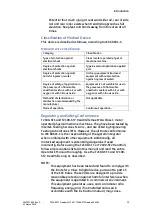
Page 14: ...he customer or user of the T2100 ST Series should ensure that it is used in such an environment Emissions Test Compliance Electromagnetic Environment Guidance RF Emissions CISPR 11 Group 1 The T2100 ST Series uses RF energy only for its internal function Therefore its RF emissions are very low and are not likely to cause any interference in nearby electronic equipment RF Emissions CISPR 11 Class B...

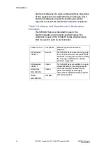
Page 15: ...power quality should be that of a typical commercial or hospital environment Surge IEC 61000 4 5 1kV Differential 2kV Common 1kV Differential 2kV Common Mains power quality should be that of a typical commercial or hospital environment Voltage Dips Dropout IEC 61000 4 11 95 Dip for 0 5 Cycle 60 Dip for 5 Cycles 30 Dip for 25 Cycles 95 Dip for 5 Seconds 95 Dip for 0 5 Cycle 60 Dip for 5 Cycles 30 D...

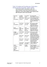
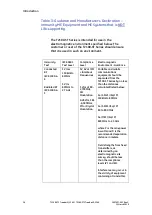
Page 16: ... RF IEC 61000 4 3 3 Vrms 150 kHz to 80 MHz 3 V m 80 MHz to 2 7 GHz 3V 6V at ISM Amateur Frequencies 3 V m at 80 2 700MHz AM Modulation 9 28V m 385 6 000MHz FM or Digital Modulation Portable and mobile communications equipment should be separated from the T2100 ST Series by no less than the distances calculated listed below D 3 5 V1 Sqrt P 150kHz to 80MHz D 3 5 E1 Sqrt P 80 to 800 MHz D 7 E1 Sqrt P...

Page 17: ...er of the communications equipment Max Output Power Watts Separation m 150kHz to 80MHz D 3 5 V1 Sqrt P Separation m 80 to 800MHz D 3 5 E1 Sqrt P Separation m 800MHz to 2 5GHz D 7 E1 Sqrt P 0 01 0 11667 0 11667 0 23333 0 1 0 36894 0 36894 0 73785 1 1 1667 1 1667 2 3333 10 3 6894 3 6894 7 3785 100 11 667 11 667 23 333 Responsibility of the Manufacturer Full Vision Inc is responsible for the effects ...

Page 18: ...d seek factory authorized repair before attempting to restart the treadmill Never allow children or pets near the machine without qualified adult supervision Note the location of stop and or emergency stop controls and their operation before starting a test or workout This device is not intended for use by persons with reduced physical sensory or mental capabilities or lack of experience and knowl...

Page 19: ... provider Always unplug the T2100 ST Series Treadmill when servicing inspecting or cleaning the treadmill Routinely inspect the treadmill for loose parts Inspect handrails and ensure they will support the patient properly Always start the running belt at its slowest speed before starting the patient test Do not step onto belt when it is moving Always slow the running belt to its minimum speed befo...

Page 20: ...your device or packaging that is in black and white indicates a potential hazard and is a caution Symbols Symbol Description Catalog or Orderable Part Number Indicates the manufacturer s catalog or part number Serial Number Indicates the manufacturer s serial number Date of Manufacture Year Month Indicates the original manufacture date for this device Manufacturer Name and Address Indicates the na...

Page 21: ...and disposed of in accordance with your local requirements and sources The EEE program minimizes any potential effects on the environment and user health by eliminating the potential presence of hazardous substances in the waste stream Customers should contact their local authorities or T2100 Distributor for guidance in complying with the directive Keep Dry Indicates that you need to keep the cont...

Page 22: ...of the medical device Label Locations This section identifies the labels and their locations on the product and packaging Refer to the previous illustrations for the locations of the labels identified in the following table For detailed descriptions of the symbols that appear on the labels refer to Symbols on page 20 Item Label Location Description 1 Front of device Identifies the product model 2 ...

Page 23: ... 6 Front of device Identifies Power switch 7 Shipping Package Identifies the following information for shipping Model number Reference number Serial number Storage conditions Regulatory compliance Country of origin EC Representative information 8 Front of device Identifies Unique Device Identifier Equipment Identification Product Label Product Label Format Item Name Description 1 Manufacturer Full...

Page 24: ...lthcare or its authorized representatives Service Requirements Failure on the part of the responsible individual hospital or institution using this equipment to implement a satisfactory maintenance schedule may cause undue equipment failure and possible safety hazards Regular maintenance irrespective of usage is essential to ensure that the components of this system are always functional when requ...

Page 25: ...thcare Diagnostic Cardiology product documents Convention Description Bold Text Indicates keys on the keyboard text to enter or hardware items such as buttons or switches on the equipment Italicized Bold Text Indicates software terms that identify menu items buttons or options in various windows KEY1 KEY2 Indicates a keyboard operation A plus sign between the names of two keys indicates that while...

Page 26: ...ows NOTE The tip or additional information appears indented below the NOTE flag word Related Documents The following documents are referenced in this manual and provide additional information that may be helpful in the installation configuration maintenance and use of this product Part Number Title 2097937 001 T2100 ST1 T2100 ST2 Operator s Manual English 2097937 021 T2100 ST1 T2100 ST2 Operator M...

Page 27: ...anual Polish 2097937 201 T2100 ST1 T2100 ST2 Operator Manual Portuguese EU 2097937 191 T2100 ST1 T2100 ST2 Operator Manual Romanian 2097937 221 T2100 ST1 T2100 ST2 Operator Manual Russian 2097937 231 T2100 ST1 T2100 ST2 Operator Manual Serbian 2097937 241 T2100 ST1 T2100 ST2 Operator Manual Slovak 2097937 261 T2100 ST1 T2100 ST2 Operator Manual Swedish 2097937 251 T2100 ST1 T2100 ST2 Operator Manu...

Page 28: ......

Page 29: ...l devices and are compatible with CASE CardioSoft CS MAC 5500 and MAC 2000 References to left right front and rear assume that you are standing on the treadmill facing the handrails All parts listed below are considered Patient Applied Parts except where noted Item Description 1 Emergency Stop Button 2 Patient Handrails 3 Stop Tether 4 Side Rail 5 Running Belt 6 Elevation Landing Gear Non Applied ...

Page 30: ...ht capacity 500 lb 227 kg All steel construction with powder coat finish Treadmill net weight 425 lb 193 kg Drive System Heavy duty 6 peak hp brushless DC servo motor T2100 ST1 110 120VAC single phase 60 Hz 20 amp power supply T2100 ST2 200 240VAC single phase or split phase 50 60 Hz 15 amp power supply Speed Range 0 1 to 15 0 mph 0 2 to 24 0 km h self calibrating and adjustable in 0 1 mph 0 1 km ...

Page 31: ...152m Power Requirements The T2100 ST1 is designed to operate on dedicated 100 130 VAC 20 amp power and the T2100 ST2 is designed to operate on dedicated 200 to 264 VAC 13 amp power Make sure that the treadmill is connected to an outlet that looks like one of the following illustrations T2100 ST1 Power Consumption 1934 watts 6600 BTU 20 amps T2100 ST2 Power Consumption 2580 watts 8804 BTU 13 amps T...

Page 32: ...0 VAC Type L ITALY 250 VAC Type J SWISS WARNING The T2100 ST1 and T2100 ST2 treadmills must be grounded to reduce the risk of electrical shock If a malfunction occurs grounding provides a path of least resistance for an electric current Ungrounded connections must not be used No other equipment may be used on the electrical circuit with the treadmills Do not use extension cords Using a shared or u...

Page 33: ...Product Overview 2097937 002 Rev G T2100 ST1 Treadmill 110V T2100 ST2 Treadmill 220V 33 11 March 2019 NOTE The T2100 ST1 and T2100 ST2 Treadmills must have their own dedicated power outlet ...

Page 34: ......

Page 35: ...e treadmill to the area by rolling it on its front wheels If your treadmill must pass through a door opening less than 36 wide additional disassembly by removal of the handrails is required Refer to Removing and Reinstalling the Handrails for Moving on page 154 This task should be performed by an authorized service provider to ensure that the T2100 ST1 and T2100 ST2 are properly reassembled and fu...

Page 36: ... assembly to a comfortable height keeping knees bent and back straight as you lift Rotate the treadmill in the direction you want to go the treadmill will pivot on its wheels and push forward When you have maneuvered the treadmill into its location gently lower the end of the bed assembly to the floor Initial Setup Tools required for assembly 5 16 Allen wrench supplied The treadmill is shipped wit...

Page 37: ...ill edges to any obstruction for dismount and safety purposes Observe that the operator should be stationed by the Emergency Stop Button ESB WARNING The T2100 ST1 and T2100 ST2 treadmills conform to FCC class B rating for electromagnetic emissions It is recommended not to place the treadmill closer than 5ft 1 5m from sensitive electronic devices within the room or in an adjacent room If an interfe...

Page 38: ...he equipment is properly wired For international wiring test refer to the internal standards agencies of that particular country NOTE The AC Line Voltage test is required at the time of installation 100 to 130 VAC 60 Hz Using a digital voltmeter set to measure at least 200 VAC to check the voltage of the NEMA 5 20R AC wall outlet U S only or applicable international connection dedicated 20 amp ser...

Page 39: ...Test below or the test method that is required by your Country Local governing safety organization For international power cords refer to the internal standards agencies of that particular country Ground Continuity Test This test verifies that there is continuity less than 100 mΩ resistance between exposed metal surfaces which have the potential to become energized and the ground prong on the main...

Page 40: ...e which tests apply to the unit under test and the maximum allowable leakage currents For international leakage limits refer to the internal standards agencies of that particular country If the unit under test fails the leakage tests do not allow the customer to use the equipment Call Tech Support for assistance GE Healthcare recommends that you perform these tests Before applying power for the fi...

Page 41: ...erse Polarity L2 L1 NC _________μA Pass Fail 500μA Ground Continuity Resistance 1 AC mains power cord ground prong to exposed metal surface ground lug N A ________mΩ Pass Fail 100mΩ WARNING Total system leakage current must not exceed 500 microamperes Leakage Test Diagrams These diagrams show only a representation of how a typical leakage current tester functions Follow the instructions provided w...

Page 42: ...our treadmill for the first time you may need to adjust the tracking of the belt to conform to your floor You may also need to adjust the tracking if you move the machine to another location See Running Belt Tracking Adjustment on page 59 for details Running Belt Tension Adjustment Your running belt has been pre tensioned at the factory and run for 16 hours prior to shipment It may however be nece...

Page 43: ...est plug that enables you to test the operation of the treadmill without the host controlling device attached The plug is located on the left side of the treadmill secured to the frame by Velcro The plug is to be used only for testing the treadmill Do not stand on or use the treadmill while testing Item Description 1 Test Plug Location on Left 2 Circuit Breaker Array 3 Incoming Power Cord 4 Main P...

Page 44: ...ug in the test connector into the RS232 port 3 Press and hold the button on the test connector and turn the treadmill power ON Continue holding until the treadmill begins to elevate 4 When the treadmill begins to raise repeatedly press the button to cycle through the different phases of the test The following table shows the sequence of self test stages Stage Incline Speed mph 1 5 0 0 2 10 0 0 3 1...

Page 45: ...nect the RS232 or USB interface cable from the host computer You are ready to begin the set up procedure prescribed by your medical test equipment supplier Setup and Connection to Host Currently four GE host stress systems can connect to the T2100 ST series treadmill and are used as controlling devices CASE CardioSoft CS MAC 5500 and MAC 2000 CASE connection and setup 1 Connect one end of the RS23...

Page 46: ... automatically and the Windows screen opens 5 Log in when prompted Refer to the CASE Operator s Manual for logon instructions 6 If not already in the software application double click the CASE icon The CASE initial screen opens CASE Initial Screen NOTE Depending on the version of software and user preferences the initial screen will vary 7 On the upper right side of the screen click the System Con...

Page 47: ...the CASE device operating instructions should be referenced for controlling the treadmill with the CASE application CardioSoft CS connection and setup To communicate to the T2100 ST1 or T2100 ST2 treadmill using the USB port you will need to install the appropriate USB driver software on your host computer The USB driver is supplied on the provided flash drive When connecting to the USB port ensur...

Page 48: ...he flash drive and locate the file named CDM21218_Setup exe and double click it to start the installation NOTE Do not download the driver from the FTDI website NOTE The following instructions are for a PC running Windows 7 The basic instruction flow should be the same for Windows 8 and 10 although the screens may vary If necessary refer to Appendix B Reference Documents for a list of reference doc...

Page 49: ...bly and Setup 2097937 002 Rev G T2100 ST1 Treadmill 110V T2100 ST2 Treadmill 220V 49 11 March 2019 5 Click Extract The Device Driver Installation Wizard opens 6 Click Next The License Agreement window opens ...

Page 50: ... Rev G 11 March 2019 7 Select I accept this agreement and click Next An installation progress window opens The installation process should take less than a minute When the installation is complete the Device Driver Installation Wizard window opens confirming a successful installation ...

Page 51: ...oSoft CS PC and the monitor 5 On the CardioSoft CS PC determine the COM port that the USB Serial Port is using by doing the following a On the CardioSoft CS PC click Start and in the Search programs and files field type Device Manager and press Enter The Device Manager window opens b Scroll to Ports COM LPT c Find the USB Serial Port in the list The port number is given in the parenthesis NOTE Thi...

Page 52: ...tial screen opens CardioSoft Initial Screen NOTE Depending on the version of software and user preferences the initial screen will vary 7 On the upper right side of the screen click the System Configuration button Depending on the version of software the button may look like one of the following The System Configuration window opens 8 Click the Devices tab 9 The COM port number is displayed in the...

Page 53: ...ick OK to close the System Configuration window and return to the CardioSoft or CS initial screen If needed the CardioSoft CS operating instructions should be referenced for controlling the treadmill with the CASE application MAC 5500 ST connection and setup NOTE Prior to starting this section confirm the MAC 5500 device contains the ST Stress Test System option The device can be identified by the...

Page 54: ... 108 to the COM1 port on the MAC 5500 ST unit MAC 5500 Rear View 4 Make sure the treadmill is connected to AC power 5 Turned the power ON at the treadmill 6 If necessary turn on the MAC 5500 ST device with the power button on the keyboard Refer to the MAC 5500 operator s manual for instructions on conducting an exercise stress test MAC 2000 ST connection and setup NOTE Prior to starting this secti...

Page 55: ...M port located on the lower front panel of the treadmill 3 Connect the other end of the RS232 serial cable GE part number 2097829 110 to the COM B port on the MAC 2000 ST unit MAC 2000 Rear View 4 Make sure the treadmill is connected to AC power 5 Turn the power ON at the treadmill 6 If necessary turn on MAC 2000 ST with the power button on the keyboard Refer to the MAC 2000 operator s manual for ...

Page 56: ......

Page 57: ...rocedures other than normal maintenance are performed by an authorized and qualified service provider Contact your local GE customer support representative Use only authorized replacement parts Using other parts may void your warranty and may cause your T2100 ST1 or T2100 ST2 treadmill to malfunction Daily Maintenance Wipe the treadmill to remove soil moisture and perspiration Disinfect the hood a...

Page 58: ...acking setting Check running belt tension Observe running belt tracking and correct as required Monthly Maintenance Inspect and clean the running belt Semiannual Maintenance Evaluate the condition of the deck and running belt Adjust the running belt to assure proper alignment Check the running belt adjustment Check the drive belt tension adjustment Clean and lubricate the treadmill elevation screw...

Page 59: ... right is normal during use Do not allow the running belt to travel all the way to either side To adjust the belt tracking do the following 1 Turn the treadmill s power switch to ON 2 Increase the speed to 3 mph 4 8 km h 3 Observe the left side of the running belt as it travels over the rear roller If the belt runs to the right side of the roller turn the right bolt 1 8 turn clockwise and turn the...

Page 60: ... is noticeable when the belt tends to hesitate or stick Adjust the tension on the belt by following the procedure and referring to the illustration above 1 Turn the treadmill s power switch to ON 2 Start the treadmill and increase to 1 mph 1 6 km h 3 Start walking on the treadmill grabbing side handrail and applying pressure with your foot to create resistance on the running belt 4 If the running ...

Page 61: ...located on the bottom hood with 1 8 Allen wrench 2 With the socket and wrench loosen the TENSION ADJUSTMENT back nut 3 Press down on drive belt between motor and front roller with approximately 5lbs of force to achieve to 3 8 4 If adjustment is need using a wrench turn the TENSION BOLT clockwise to tighten To loosen turn the wrench counter clockwise 5 Make small adjustment until the drive belt def...

Page 62: ...ain DO NOT use disinfection with a phenol base or peroxide compound to disinfect the external surface Elevation Screw Lubrication The Elevation Screw must be cleaned and lubricated every 6 months to maintain proper operation of the treadmill Failure to perform this maintenance function will result in premature wear and ultimate failure of the lift mechanism This procedure requires the following to...

Page 63: ... the warranty Using such sprays can bring about surface changes that may result in hesitation or excessive belt slip Prolonged use in high speed running may cause hesitation slippage on each foot plant Inspect the running deck for factory lubrication on running surface For troubleshooting refer to Running Belt High Speed Application on page90 If the running deck surface becomes grooved due to wear...

Page 64: ......

Page 65: ...serial port or USB port The communication protocol is based on the industry standard In addition to the physical interfaces with the controlling system PC the motor controller and elevation motor the UPS also includes an interface to an emergency stop switch and an SD card Scope This chapter applies only to the electronic control for the T2100 ST1 and T2100 ST2 treadmills Specifications for the me...

Page 66: ...f Operation 66 T2100 ST1 Treadmill 110V T2100 ST2 Treadmill 220V 2097937 002 Rev G 11 March 2019 T2100 ST Series Block Diagram 4th Edition Smart Power Supply FGLF0495 3 3 1 Edition Smart Power Supply FGLF0495 1 ...

Page 67: ...nd the outputs to raise or lower the elevation based on the current set points for speed and elevation Through the use of either communication port the unit accepts commands to modify the belt state the belt speed and the deck elevation The current state of the control may also be queried through the use of this serial port As commands are received to change the set point speed or set point grade ...

Page 68: ...ontrol The belt enable output must be energized to put the belt into a run mode The speed control output is a 4kHz 1024 count pulse width modulated PWM output supplied directly to the motor controller Based on calibration the speed is controlled by outputting a PWM speed reference to the motor controller and enabling the belt run output The speed inputs are averaged over a two second period to pro...

Page 69: ...time the elevation motor is disengaged until another set point position is requested ESTOP The emergency stop switch will remove power from the treadmill control board to guarantee a stop condition When this occurs and the emergency stop button is subsequently released the control will be in the same state as when the unit is powered up using the main power switch Therefore it is necessary in eith...

Page 70: ...f the RS 232 serial port Note that it is not possible to enter self test using the USB port If the RS 232 lines are determined to be shorted the UPS enters the self test mode During the self test mode 14 stages of speed and elevation set points are used to exercise the inputs and outputs Upon completion of each new set point another character is sent out and the process is repeated to advance to t...

Page 71: ... the ON position This configuration is compatible with the GE Protocol Firmware Version 1 57 and later FGLF0495 1 Smart Power Supply Additional dip switch on UPS Firmware Version 1 1812 and later FGLF0495 03 Smart Power Supply This configuration has 1 6 number switch Switch 1 2 4 5 and 6 are in the OFF position and switch 3 is in the ON position When retrieving system flash log file switch configu...

Page 72: ...e signal is toggled between the motor controller s signal reference voltages 5Vdc The maximum current for this output is 2mA and the maximum voltage is 15Vdc D Serial Port Output An electrically isolated RS 232 level not to exceed 10VDC is provided to the host controller E USB Port Output An electrically isolated USB port to the host controller not to exceed 5V or 100mA Electrical Connections A In...

Page 73: ...rd with 2 ounce copper B Galvanic isolation between the AC power circuits and the low voltage electronic circuits should be guaranteed C Outer Dimensions 6 T x 9 W x 2 5 D max D Mounting position The board shall be capable of being mounted with the PCB either parallel or perpendicular to the bottom pan of the treadmill E Environment 0 70 C ambient temperature F High level vibrations from adjacent ...

Page 74: ......

Page 75: ...79 When you receive an error code from the T2100 ST series treadmill use the flowcharts in this chapter to help you identify and resolve the error Descriptions of the error codes are provided in this chapter There are two methods for using the flowcharts If you know the failure mode causing the issue scan the flowchart titles for that failure mode and review the corresponding flowchart If you are ...

Page 76: ...art Power Supply FGLF0495 03 Error Code 2 Flow Chart 1KK Elevation Error 2 on page 89 02 Treadmill will increase elevation but will not decrease elevation Smart Power Supply Relay Activation Smart Power Supply Error Code 2 Flow Chart 1K Elevation Error 2 on page 88 Smart Power Supply FGLF0495 03 Error Code 2 Flow Chart 1KK Elevation Error 2 on page 89 02 Treadmill would not elevate under heavy loa...

Page 77: ...er Supply Error Code 4 Flow Chart 1M Over Speed Motor Controller Error 4 on page 91 06 07 Treadmill running belt shutdown above 6 mph Smart Power Supply Error Code 6 Flow Chart 1O Over Speed External Sensor Error 6 on page 93 Smart Power Supply Error Code 7 Flow Chart 1P Speed Compare Error 7 on page 94 09 Treadmill will start belt after cycling the Emergency Stop Button Smart Power Supply Error C...

Page 78: ...breaker lit Go To Chart 1B No Yes Turn treadmill power switch to the off position 0 Disconnect power cord from treadmill and wall outlet Measure continuity thru the 20amp circuit breaker Turn treadmill power switch is in the on 1 position Check power cord for damage No Yes Circuit breaker has continuity No Yes Replace power cord Replace 20amp Circuit Breaker Verify the power cord is plugged in tre...

Page 79: ...een LED1 lit on Drive PC2303 012 N No Turn treadmill power switch in the on 1 position Is the Red D7 LED lit on Smart Power Supply No Yes Is the Green LED1 lit on Drive PC2303 012 N Is the Red D7 LED lit on Smart Power Supply Yes Verify Inline filter continuity thru filter Does the Inline filter have continuity No Replace Inline Filter Verify treadmill power switch is in the off 0 position Yes Go ...

Page 80: ...on Drive PC2303 012 N Turn treadmill power switch in the on 1 position No Yes Is the Green LED1 lit on Drive PC2303 012 N Verify incoming voltage 110 120VAC Verify incoming voltage 220 240VAC No Yes Is Voltage between Black and Brown wire 110 120VAC Replace Drive PC2303 012N Green Light should be lit on Drive PC2303 012 N Reference 1C No Yes Is Voltage between Black and Brown wire 220 240VAC Volta...

Page 81: ...are not tripped No Yes Is the Red D7 LED lit on Smart Power Supply PCBLF0443 1 Verify incoming voltage 110 120VAC Verify incoming voltage 220 240VAC No Yes Is Voltage between Red and Blue wire 110 120VAC Replace Smart Power Supply PCBLF0443 1 Red D7 LED Light should be lit on Smart Power Supply PCBLF0443 1 Reference 1D No Yes Is Voltage between Red and Blue wire 220 240VAC Turn treadmill power swi...

Page 82: ... Verify the continuity of the Emergency Stop Harness with an OHM meter to ensure the wire is not damaged Turn treadmill power switch in the on 1 position Verify wire connectors on the Emergency Stop and quick disconnect on connector J4 J5 are a secure connection on Smart Power Supply PCBLF0443 1 No Yes Is the Red D13 LED lit on Smart Power Supply PCBLF0443 1 Replace Emergency Stop Button Red D13 L...

Page 83: ...CBLF0443 1 Verify treadmill power switch is in the off 0 position Verify the continuity of the Emergency Stop Harness with an OHM meter to ensure the wire is not damaged Turn treadmill power switch in the on 1 position Verify wire connectors on the Emergency Stop and quick disconnect on connector J6 J7 are a secure connection on Smart Power Supply PCBLF0443 1 No Yes Is the Red D12 LED lit on Smart...

Page 84: ...ased or Pull Tether missing Press connect on the Full Vision Treadmill PS New Cal Software are you Recd and Sent information Turn treadmill power switch is in the on 1 position No Yes Verify Communication cable has not been damaged Verify Communication cable is connected at both ends Is Communication Cable Damaged No Yes Replace Communication Cable Communication should be restored Reference Chart ...

Page 85: ...en damaged Verify Communication cable is connected at both ends Is Communicatio n Cable Damaged No Yes Replace Communication Cable Communication should be restored Reference Chart 1G Is Communicatio n Cable Connected Yes Connect Communication Cable Communication should be restored Reference Chart 1G No When connecting Stress System or Full Vision Treadmill PS New Cal Software you received missing ...

Page 86: ...low Chart 1K Reason for error flashes Elevation Error 2 Reference Smart Power Supply Error Code 3 Flow Chart 1L Reason for error flashes Zero Speed Motor Controller Error 3 Reference Smart Power Supply Error Code 4 Flow Chart 1M Reason for error flashes Over Speed Motor Controller Error 4 Reference Smart Power Supply Error Code 5 Flow Chart 1N Reason for error flashes Zero Speed External Sensor Er...

Page 87: ...the Full Vision Treadmill PS New Cal software connect communication thru RS232 or USB Did treadmill cycle according to Test Plug Procedure Yes No Connect Stress System perform test Did treadmill respond to Test Procedure Yes No Return Treadmill to service Is the Red LED D13 flashing on the Smart Power Supply PCBLF0443 1 Yes Treadmill should be operational No Select the treadmill will start out slo...

Page 88: ...Troubleshooting 88 T2100 ST1 Treadmill 110V T2100 ST2 Treadmill 220V 2097937 002 Rev G 11 March 2019 Smart Power Supply FGLF0495 1 Error Code 2 Flow Chart 1K Elevation Error 2 ...

Page 89: ...Troubleshooting 2097937 002 Rev G T2100 ST1 Treadmill 110V T2100 ST2 Treadmill 220V 89 11 March 2019 Smart Power Supply FGLF0495 03 Error Code 2 Flow Chart 1KK Elevation Error 2 ...

Page 90: ...d be operational No Send a Start Belt Command or Press Start if equipped with controller Did the running belt start Return Treadmill to service Replace Drive PC2303 012 N Yes No Verify the harness between Drive PC2303 012 N and Smart Power Supply PCBLF0443 1 is properly connected and not damaged Was the harness damaged Turn the treadmill power switch ON Was the harness properly connected Replace H...

Page 91: ... power switch OFF O for 10 seconds then turn the power switch ON Is the Red LED D13 on the Smart Power Supply PCBLF0443 1 on continuously Yes No Is the Red LED D13 flashing on the Smart Power Supply PCBLF0443 1 Yes Treadmill should be operational No Send a Start Belt Command or Press Start if equipped with controller increase speed to 10mph With the treadmill running at 10 0 mph for 1 minute is th...

Page 92: ... or Press Start if equipped with controller Speed the treadmill up to 1 mph With the treadmill running at 1 0 mph for 1 minute is the Red LED D13 on Replace Speed Sensor Yes Verify that the speed sensor gap to flywheel magnet is 1 4 and connector is secure on J10 on the Smart Power Supply PCBLF0443 1 Verify when the fly wheel magnet passes by the speed sensor that D10 LED on the Smart Power Supply...

Page 93: ...r gap to flywheel magnet is 1 4 and connector is secure on J10 on the Smart Power Supply PCBLF0443 1 Verify when the fly wheel magnet passes by the speed sensor that D10 LED on the Smart Power Supply PCBLF0443 1 the red led light is on then goes out after the speed is not present Send a Start Belt Command or Press Start if equipped with controller Speed the treadmill up to 10 mph With the treadmil...

Page 94: ...ness between Drive PC2303 012 N and Smart Power Supply PCBLF0443 1 is properly connected and not damaged Was the harness damaged Was the harness properly connected Replace Harness 10 Pin Harness Yes No Connect harness Verify the harness between Motor PMC5FA 00101 03 and Drive PC2303 012 N is properly connected and not damaged No Yes Was the harness damaged Was the harness properly connected Replac...

Page 95: ...ly PCBLF0443 1 Verify when the fly wheel magnet passes by the speed sensor that D10 LED on the Smart Power Supply PCBLF0443 1 the red led light is on then goes out after the speed is not present Is the Red LED D10 on the Smart Power Supply PCBLF0443 1 flashing ON Off when passing by flywheel magnet Yes No Replace Smart Power Supply Send a Start Belt Command or Press Start if equipped with controll...

Page 96: ... flashing on the Smart Power Supply PCBLF0443 1 Yes Treadmill should be operational No Send a Start Belt Command or Press Start if equipped with controller Did the running belt start Return Treadmill to service Replace Drive PC2303 012 N Yes No Verify the harness between Drive PC2303 012 N and Smart Power Supply PCBLF0443 1 is properly connected Turn the treadmill power switch ON Was the harness p...

Page 97: ...LF0443 1 on continuously Yes No Is the Red LED D13 flashing on the Smart Power Supply PCBLF0443 1 Yes Treadmill should be operational No Send a Start Belt Command or Press Start if equipped with controller increase speed to 10mph With the treadmill running at 10 0 mph for 1 minute is the Red LED D13 on Return Treadmill to service Replace Interface cable Yes No Inspect interface cable between the T...

Page 98: ...us Over Voltage Self Resetting 8 Blink Output Short Circuit Latched See Note 1 Note 1 Contact local GE customer support representative for possible Drive PC2303 012 N replacement Running Belt High Speed Application When operation the treadmill at a High Speed Application The running belt is displaying hesitation slippage of the running belt with each foot plant The following may be detected Inspec...

Page 99: ... IC3 then powerup the treadmill Depending on the number of records to be written it can take up to 2 minutes to finish When complete the treadmill begins to initialization by turning the down relay on Once that is done power the treadmill down and retrieve the micro SD card Then reset the switch configuration 1 2 4 5 and 6 are in the OFF position and switch 3 is in the ON NOTE The system flash log...

Page 100: ...ble Units This chapter lists the parts that can be replaced onsite identifies their locations and provides their orderable part numbers Final Assembly OUTSIDE CONTACT CONNECT CABLE TO PULL TETHER CONNECT CONTACT I I ROUTE THROUGH LEFT HANDRAIL CONNECT CABLE TO ESB ROUTE WIRES THROUGH CENTER LEFT HANDRAIL DETAIL 1 SEE DETAIL 1 ...

Page 101: ...9 067 1 8 Handrail Center 2097829 068 1 10 12 Emergency Stop with Guard Assembly 2097829 011 1 10 11 Pull Tether Assembly 2097829 026 1 19 20 21 28 29 Hood Kit Assembly 2097829 069 1 30 Comm Cable Clamps 2097829 074 1 22 23 24 Test Plug 2097829 070 1 4 7 9 13 16 18 23 24 Final Assembly Hardware Kit 2097829 071 1 CONNECT EMERGENCY STOP CABLE TO J4 J5 CONNECT PULL TETHER CABLE TO J7 J6 Note Circuit ...

Page 102: ...6A C19 GB 1002 2097829 107 POWER CORD 250VAC 13A TYPE K DANISH 2097829 112 POWER CORD 250VAC 16A TYPE J SWISS 2097829 113 POWER CORD 250VAC 16A TYPE H ISRAEL 2097829 114 POWER CORD 250VAC 15A TYPE L ITALY 2097829 115 POWER CORD 250VAC 15A TYPE N BRAZIL 2097829 116 Not shown Grease tube 2097829 072 1 For Reference Manufacture s Description for individual items Item Manufacturer s Description Qty 2 ...

Page 103: ...C19 AS NZS 3112 POWER CORD 250VAC 16A C19 GB 1002 POWER CORD 250VAC 13A TYPE K DANISH POWER CORD 250VAC 16A TYPE J SWISS POWER CORD 250VAC 16A TYPE H ISREAL POWER CORD 250VAC 15A TYPE L ITALY POWER CORD 250VAC 15A TYPE N BRAZIL 16 Clamp Support 1 17 Lock Washer 1 18 Bolt HHCS 20 x Lg Gr 5 1 19 Hood T2100 ST Series with GE 80mm Logo 1 20 Decal Caution 1 21 Screw HHWHTS 8 32 x 3 8 Lg 5 22 Test Plug ...

Page 104: ...1 75 Dia with Stud 2097829 058 1 STRETCH ADJUSTMENT MARKS 4X INSTALL CAMBER SEE NOTE 3 NOTES 1 ADJUSTMENT SCREWS MUST BE MATCH TIGHTENED PROPER TENSION IS ACHIEVED WHEN BELT CAN T SLIP ON PULLEYS WHEN IN OPERATION ACHIEVED 2 ADJUST DRIVE BELT TENSION PULLING ALL FREE PLAY OUT OF BELT DO NOT OVER TIGHTEN CAUSING THE BELT TO STRETCH 3 MOVE REAR PULLEY SIDE TO SIDE IN CHANNELS TO OBTAIN FRONT TO REAR...

Page 105: ...or individual items Item Manufacturer s Description Qty 1 Not orderable as FRU 2 Belt Running with V Guide 1 3 Bolt HHCS 5 16 18 x 75 Lg 6 4 Lock Washer 5 16 Dia 7 5 Flat Washer 5 16 Dia 9 6 Deck Support Channel Weldment 3 7 Deck Isolator 1 75 Dia with Stud 6 8 Flange Lock Nut HNS 5 16 18 6 9 Deck Running Board 1 10 Screw HSFCHCS 5 16 18 x 1 5 Lg PLTD 6 11 Roller Front 1 12 Set Screw 5 16 18 x 1 7...

Page 106: ...Field Replaceable Units 106 T2100 ST1 Treadmill 110V T2100 ST2 Treadmill 220V 2097937 002 Rev G 11 March 2019 Frame Assembly APPLY MOLY BASED GREASE 2X ...

Page 107: ...urer s Description Qty 5 Stem Bumper 2 8 Bolt HHCS 20 x 75 Lg Gr 5 26 9 Flat Washer Dia 26 10 Lock Washer Dia 26 11 Nut HN 20 Grade 5 26 13 Bumper 1 8 Dia Black 2 14 Shoulder Bolt HSHSS 5 8 Dia x 1 Lg 2 15 Elevation Delrin Spacer 4 16 Flat Washer Dia 2 17 Nylon Lock Nut NLN 13 2 18 Bolt HHCS 3 8 16 x 3 Lg Grade 5 1 19 Washer Nylon 4 20 Nylon Lock Nut 3 8 16 1 21 Belt Drive 1 ACTUATOR INSTALLATION ...

Page 108: ... Slip Safety Walk Cut 1 5 x 4 2 1 2 3 4 6 7 12 Not orderable as FRU Motor Pan Assembly Orderable FRUs Item Description GE Orderable Number Qty 7 Actuator 115V or Actuator 115V MSI for T2100 ST1 only 2097829 028 or 2097829 088 1 DC MOTOR MOUNT ASSEMBLY CIRCUIT BOARD MOUNT ASSEMBLY TAP 10 32 HOLE AND SAND POWDER COAT MATERIAL FOR PROPOR GROUND CONNECTION ...

Page 109: ...mp 2097829 034 1 25 Breaker 1 4 amp 2097829 035 1 27 Switch TA35 C324 L200C0 2097829 036 1 30 Power Cord Inlet C 20 4793 4000 2097829 037 1 4 5 21 22 Motor Pan Isolation Kit 2097829 038 1 2 3 6 8 11 13 14 16 17 21 22 23 26 28 29 31 Motor Pan Hardware Kit 2097829 039 1 For Reference Manufacture s Description for individual items Item Manufacturer s Description Qty 2 HHCS 20 x 1 25 Lg Gr 2 3 3 FW Di...

Page 110: ...X 50 Lg 7 18 Filter CorCom F4635 or 10EHT1 NOTE F4635 is being replaced by backward compatible 10EHT1 part 1 19 20 Drive DC Servo PC2303 012 N with Regen Model RA2302 1 21 RHMS 10 32 X 375 LG 6 22 NYLON ISOLATOR 10 32 5 23 Plate Breaker Trackmaster 1 24 Breaker 3 amp 2 25 Breaker amp 2 26 HHWHTS 8 32 x 375 Lg 2 27 Switch TA35 C324 L200C0 1 28 RHMS 6 32 x 50 Lg 2 29 K Lock Nut 6 32 2 30 POWER CORD ...

Page 111: ...ECTOR 115V CONFIGURATION220V CONFIGURATION RESITOR OMITE DRIVE DC SERVO PC2303 012 N BLACK 110 120 BLANK BROWN HOT BLANK BLANK BLACK 208 240 BROWN HOT BLANK WHITE COMMON RED INCLINE UP BLACK INCLINE DOWN CONNET COLOR CONFIGURATION CONNECT 2 PIN CONECTOR BROWN WIRE ON TOP ORANGE WIRE ON TOP ITEM 12 SHEET 1 OF 2 CIRCUIT BOARD ASSEMBLY MULTIPLE GROUND CONNECTION DC FAN WIRE BLACK DC FAN WIRE RED Gap ...

Page 112: ...stor 2097829 042 1 BREAKER 3 AMP BREAKER AMP BLK WHT BLK RED BRN BRN BRN BLU FILTER CORCOM F4635 10EHT1 HARNESS CONNECTOR BLACK HARNESS CONNECTOR BROWN DRIVE DRIVE GROUND ON NYLON STANDOFF CIRCUIT BOARD ASSEMBLY RED INCLINE COMMON WHITE AC COMMON BLUE INCLINE HOT BROWN AC HOT CONNECTOR COLOR CONFIGURATION HARNESS JUMPER BROWN HARNESS JUMPER BLACK GROUND HARNESS GRN YEL MAIN WIRE HARNESS GRN YEL MA...

Page 113: ...6 Cable USB Panel to USB B 2097829 050 1 1 2 7 9 11 12 17 23 Motor Pan Assembly Wiring Hardware Kit 2097829 051 1 24 25 26 Relay 110V For T2100 ST1 only includes Velcro hook loop 2097829 085 1 24 25 26 Relay 220V For T2100 ST2 only includes Velcro hook loop 2097829 086 1 25 Velcro Hook x 1 wide included in the relay kit NA 26 Velcro Loop x 1 wide included in the relay kit NA NOTE When replacing ol...

Page 114: ... 8 Harness Motor Controller 1 9 Harness Ground 2 10 Harness Main DC Treadmill 1 11 Harness Jumper 2 12 LW 10 EXT Tooth 1 13 Surge Suppressor 1 15 Cable RS232 Panel Mount 1 16 Cable USB Panel to USB B 1 17 Plate RS232 USB 1 18 HHCS 8 32 x 50 Lg 2 19 HNS 8 32 Flange Nut 2 20 Decal Caution 2 21 Zip Tie 8 Lg 1 22 Zip Tie 4 Lg 1 23 RMHS 4 40 x 375 Lg 2 14 Not orderable as FRU 24 Relay 110V for T2100 ST...

Page 115: ...escription for individual items Item Manufacturer s Description Qty 1 DC Motor Base 1 2 Motor DC Servo PMCFA 00101 03 1 3 Sprocket Drive 530 5MGT 15 1 4 Flywheel DC W Magnet 50 dia 1 5 HHCS 7 16 14 x 5 Lg 1 6 NLN 7 16 14 1 7 HHCS 1 2 13 x 3 Lg All Thread 1 9 HN 1 2 13 Gr5 1 NOTES 1 WHEN INSTALLING THE FLYWHEEL DRIVE SPROCKET TIGHTEN SET SCREWS ON KEY WAY FIRST AND THEN TIGHTEN THE SECOND SET SCREW...

Page 116: ... V1 66 2097829 022 1 3 8 Circuit Board Assembly Hardware Kit for FG0495 1 2097829 023 1 For Reference Manufacture s Description for individual items Item Manufacturer s Description Qty 2 Board FG0495 1 Universal Power Supply 1 3 HN 8 32 Nylon 4 4 Mount Inverter Isolation 4 5 HHWHTS 8 32 x 375 4 6 RHMS 6 32 x 2 5 Lg 1 7 Standoff Round 50 Lg 166 ID 1 8 K Lock Nut 6 32 1 1 9 Not orderable as FRU NOTE...

Page 117: ...829 080 1 3 6 Circuit Board Assembly Hardware Kit for FG0495 3 2097829 081 1 NOTE When replacing FGLF0495 1 universal power supply with FGLF0495 3 new circuit board assembly hardware kit 2097829 081 may be needed For Reference Manufacture s Description for individual items Item Manufacturer s Description Qty 2 Board FG0495 3 Universal Power Supply 1 3 HN 8 32 Nylon 5 4 Mount Inverter Isolation 5 5...

Page 118: ...scription GE Orderable Number Qty 3 Wheel Landing Gear 2097829 024 1 2 4 5 Elevation Assembly Hardware Kit 2097829 025 1 For Reference Manufacture s Description for individual items Item Manufacturer s Description Qty 2 Spanner Wheel 2 3 Wheel Landing Gear 2 4 HHCS 3 8 16 x 3 25 Lg Gr5 2 5 NLN 3 8 16 2 1 Not orderable as FRU APPLY MOLY BASED GREASE 2X ...

Page 119: ...escription GE Orderable Number Qty 1 4 Pull Tether Assembly 2097829 026 1 For Reference Manufacture s Description for individual items Item Manufacturer s Description Qty 1 Tether Pull w Wrist strap 1 2 E Stop Kill Switch LS500 1 3 Cap 1 50 x 4 00 LPDE BLK Modified 1 4 Harness ESB Pull Tether Not shown 1 ATTACHED WRIST STRAP TO CLIP WITH A DOUBLE KNOT ...

Page 120: ...tem Manufacturer s Description Qty 1 Emergency Stop IDEC 1 2 Cap 1 50 x 4 00 LPDE BLK Modified 1 3 Harness ESB Pull Tether Not shown 1 4 Decal Stop 1 5 RHMS 6 32 x Long 1 6 K Lock Nut 6 32 1 Communication Cables Orderable FRUs Item Description GE Orderable Number Qty 1 USB CABLE 5M A TO B INTERFACE T2100 ST TO CARDIOSOFT CS 2044095 001 1 2 CABLE RS232 INTERFACE T2100 ST TO CASE PC contains 2097829...

Page 121: ...0V 121 11 March 2019 Item Description GE Orderable Number Qty 4 SPARE CABLE RS232 INTERFACE T2100 ST to MAC2000ST contains 2097829 010 2097829 110 1 Calibration Software Orderable FRUs Item Description GE Orderable Number Qty 1 T2100 ST Calibration Software Version 1_0_1_8 Zip 2097829 087 1 ...

Page 122: ......

Page 123: ... Rear Roller 45 min Replacing the Running Belt 1 hr 30 min Replacing the Running Deck 30 min Replacing the Deck Cushion 1 hr 00 min Replacing the Motor Drive Belt 1 hr 20 min Replacing Adjusting the Elevation Actuator 1 hr 30 min Replacing the Smart Power Supply Relay Board 1 hr 15 min Replacing the Circuit Breaker 20 min Relocate ESB and STS 1 hr 00 min Replacing the Emergency Stop Button ESB 30 ...

Page 124: ...ng the RS232 Harness 30 min Replacing the USB Harness 30 min Replacing the Relay 110V or 220V 20 min Recalibrating Speed includes time to download software 30 min Recalibrating Speed 20 min Recalibrating Elevation included time to download software 40 min Recalibrating Elevation 30 min Comprehensive Tool List Tools o Flat head electronics screw driver 3 32 wide o Flat head screw driver 1 4 wide o ...

Page 125: ... Series Calibration Software o Stop watch or watch with a second hand o Chalk or some other temporary marking device o Serial or USB Communication Cable Replacing the Hood Tools Required o 1 4 Hex Socket or Flat Blade Screw Driver Approximate time to complete 10 min 1 Turn the treadmill s power switch to the OFF position 2 Unplug the treadmill from the wall receptacle 3 Allow the treadmill to disc...

Page 126: ...ons including wearing a grounding wrist strap that is connected to an exposed metal connection point on the treadmill chassis 7 Remove the Motor Feedback 6 pin cable on J1 from the drive 8 Remove the Motor Power 4 pin cable on TB2 from the drive 9 With the wrench and socket loosen the belt tension and slide the belt off the sprocket allowing the motor to pivot gaining access to the motor mount bol...

Page 127: ... bolt until free movement of the motor is removed 21 Reinstall the motor making sure the isolator mounts are in place When tightening the 4 bolts tighten equally without over tightening 22 Adjust the speed sensor to the magnet on the flywheel to approximately 1 4 23 Reinstall 4 plastic clamps on the Motor Feedback Power wires 24 Reconnect the Motor Feedback 6 pin cable to J1 on the drive 25 Reconn...

Page 128: ...l 110V T2100 ST2 Treadmill 220V 2097937 002 Rev G 11 March 2019 4 20 Nuts 4 Flat Washer Motor Assembly 4 Screw HHWHTS 8 32 x 3 8 lg 4 Clamp Plastic TB2 Drive Connector J1 Drive Connector 4 MTR Isolation Spacer 4 MTR Isolation Stem 4 Fender Washer 4 20 x 1 1 4 Lg ...

Page 129: ...the hood and set it aside CAUTION Use ESD precautions including wearing a grounding wrist strap that is connected to an exposed metal connection point on the treadmill chassis 7 Remove the Motor Feedback 6 pin cable on J1 from the drive 8 Remove the 10 pin communication cable on J2 from the drive 9 Remove the Incoming Power 4 pin connector on TB1 from the drive 10 Remove the Motor Power 4 pin cabl...

Page 130: ...0V T2100 ST2 Treadmill 220V 2097937 002 Rev G 11 March 2019 6 Pin J1 Connector 10 Pin J2 Connector Remove back screw Motor Power TB2 Connector Incoming Power TB1 Connector Motor Pan Drive Loosen 2 Front Screws Regen 3 Pin Connector Drive Ground to Main Wire Harness ...

Page 131: ... left and right end caps from the rear of the treadmill 7 Remove the end caps and set them aside 8 With the Allen wrench or socket completely remove the left and right tension bolts from the rear roller When removing the tension bolts maintain equal tension on the bolts to avoid stripping the threads on the tension bolt or roller 9 Push the rear roller forward as far as it will go 10 With the Alle...

Page 132: ...lace the securing screws 20 Adjust the tension of the running belt See Running Belt Tension Adjustment on page 60 Replacing the Rear Roller Tools Required o 1 4 Hex Socket or Flat Blade Screw Driver o 3 16 Hex Wrench or Hex Socket Approximate time to complete 45 min 1 Turn the treadmill main power switch to the OFF position 2 Unplug the treadmill from the wall receptacle 3 Allow the treadmill to d...

Page 133: ...13 Replace the rear roller 14 Slide the front roller between the running belt place the timing belt over the sprocket of the front roller between the running belt and place the timing belt over the sprocket of the front roller 15 Replace the front roller 16 Verify the guide for the belt deck and rollers is to the left during installation 17 Verify the timing belt goes around the front roller sproc...

Page 134: ...g the left and right end caps from the rear of the treadmill 9 Remove the end caps and set them aside 10 With the Allen wrench or socket completely remove the left and right tension bolts from the rear roller When removing the tension bolts maintain equal tension on the bolts to avoid stripping the threads on the tension bolt or roller 11 Push the rear roller forward as far as it will go 12 Lift t...

Page 135: ...o the left during installation 22 Replace the 2 deck braces and deck cushions start the deck braces securing bolts but do not tighten them 23 Replace the antistatic tinsel using the 2 from deck brace bolts 24 Replace the rear roller pushing the rear roller as far forward as possible Do not replace or start the tensioning bolts at this time 25 Verify the guide for the belt deck and rollers is to th...

Page 136: ...t on page 60 37 Reinstall the hood Running Belt Preset to 125 for proper belt tracking Front Roller See Note 2 Roller Bolt Drive Belt Flat Head Allen Screw Deck Rail Nut Deck Rail Support Running Deck Rear Roller See Note 3 Belt Tension Plate Tension Bolt See Note 1 End Cap Bolt End Cap NOTES 1 ADJUSTMENT SCREWS MUST BE MATCH TIGHTENED PROPER TENSTION IS ACHIEVED WHEN BELT CAN T SLIP ON PULLEYS WH...

Page 137: ...he 3 16 Allen wrench or socket remove the bolt securing the left and right end caps from the rear of the treadmill See the Running Belt Replacement assembly drawing on page 136 9 Remove the end caps and set aside 10 With the Allen wrench or socket completely remove the left and right tension bolts from rear roller When removing the tension bolts maintain equal tension on the bolts to avoid strippi...

Page 138: ...tension of the running belt See Running Belt Tension Adjustment on page 60 22 Reinstall the hood Replacing the Deck Cushion Tools Required o Allen Wrench or Socket o 3 16 Allen Wrench or Socket o Wrench or Socket with extension o Jack stand or block capable of supporting the weight of the rear of the treadmill Approximate time to complete 1 hr 00 min 1 Elevate the treadmill to 12 2 Turn the treadm...

Page 139: ...ill 15 With the socket remove the rubber deck cushion s from the brace 16 Replace the damaged deck cushion and use the socket to remove the bolt securing the rubber deck cushion s from the brace 17 Verify the placement of the deck cushion s Refer to the Running Belt Replacement assembly drawing on page 136 18 Replace the deck brace and deck cushions Start the deck brace securing bolts but do not t...

Page 140: ... 6 Remove the hood and set it aside CAUTION Use ESD precautions including wearing a grounding wrist strap that is connected to an exposed metal connection point on the treadmill chassis 7 With the wrench and socket loosen spring tension and the slide belt off the sprocket allowing the motor to pivot 8 With the 7 16 socket and wrench remove the 6 bolts securing the Bracket Motor Right Hand 9 Loosen...

Page 141: ...cement 2097937 002 Rev G T2100 ST1 Treadmill 110V T2100 ST2 Treadmill 220V 141 11 March 2019 Bracket Motor Right Hand Motor Tension Drive Belt 6 Bolt 1 4 20 x 1 1 4 Long 6 Bolt 1 4 Flat Washer 6 Bolt 1 4 Lock Washer 6 Bolt 1 4 20 Nut ...

Page 142: ... it aside CAUTION Use ESD precautions including wearing a grounding wrist strap that is connected to an exposed metal connection point on the treadmill chassis 7 Unplug the treadmill actuator harness The harness is a six conductor connector attached to the actuator 8 Cut the zip tie that holds the wire to the motor pan gusset 9 With the shipping blanket in suitable spot place a foot on the treadmi...

Page 143: ...on actuator perform Calibrating Elevation on page 171 Replacing the Smart Power Supply Relay Board Tools required o Wire Cutters or Utility Knife o Grounding Wrist Strap o 1 4 Hex Nut Driver or Flat Blade Screw Driver o 5 16 Hex Nut Driver o 3 32 Flat Blade Electronics Screwdriver o Grounding Wrist Strap Approximate time to complete 1 hr 15 min 1 Turn the treadmill main power switch to the OFF pos...

Page 144: ...from the SPSR Board 12 Unplug the Drive Harness J15 ten conductor spade from the SPSR Board 13 Remove the RS232 harness J13 by unscrewing the 2 flat head screws retaining it to the SPSR Board 14 Cut the Zip tie on USB harness J14 and unplug from the SPSR Board 15 Remove the two control board bracket screws 16 Remove the screw that holds the circuit board to the control board bracket 17 Relocate th...

Page 145: ...ected to an exposed metal connection point on the treadmill chassis 5 Gently pull the plate out allowing the wires to feed through the hole 6 Unplug the 2 wire connectors from the circuit breaker to be replaced When replacing more than one circuit breaker perform the replacement for one breaker at a time to keep the wires on the correct value of circuit breaker 7 Using a small electrical flat blad...

Page 146: ...er o 2 Pair Long Nose Pliers o Grounding Wrist Strap Approximate time to complete 1 hr 00 min 1 Turn the treadmill main power switch to the OFF position 2 Unplug the treadmill plug from the wall receptacle 3 Allow the treadmill to discharge for 1 minute 4 With the 1 8 Allen wrench remove the 4 10 32 screws Fig A holding the ESB and STS assembly to the fabricated handrail Fig A 10 32 Screw 1 8 Alle...

Page 147: ... wires 7 With two pairs of long nose pliers gently separate the connectors on the ESB 8 With a pair of pliers remove the STS connector from the tether assembly Fig C Fig C Fig D 9 Reverse steps 1 through 8 to reinstall the ESB and STS assembly 10 Remove the 5 hood securing bolts 11 Remove the hood and set it aside 12 Swap J4 and J5 with J6 and J7 on the controller board With the pliers cautiously ...

Page 148: ...mate time to complete 30 min 1 Turn the treadmill main power switch to the OFF position 2 Unplug the treadmill plug from the wall receptacle 3 Allow the treadmill to discharge for 1 minute 4 With a 1 8 Allen wrench remove the 2 10 32 screws Fig A holding the ESB assembly to the fabricated handrail Fig A Fig B 5 With a flat head screwdriver remove the ESB assembly from the fabricated handrail Fig B...

Page 149: ...cautions including wearing a grounding wrist strap that is connected to an exposed metal connection point on the treadmill chassis 6 Completely remove the ESB assembly and gently pull to expose the wires 7 With two pairs of long nose pliers gently separate the connectors on the ESB 8 Reverse step 1 through step 7 to reinstall the ESB assembly ...

Page 150: ...he 2 10 32 screws Fig A holding the STS assembly to the fabricated handrail Fig A Fig B 5 With a flat head screwdriver remove the STS assembly from the fabricated handrail Fig B CAUTION Use ESD precautions including wearing a grounding wrist strap that is connected to an exposed metal connection point on the treadmill chassis 6 Completely remove the STS assembly and gently pull to expose the wires...

Page 151: ...handrail before proceeding with the left and right handrails See Replacing the Center Handrail on page 153 for instructions 1 Turn the treadmill s power switch to the OFF position 2 Unplug the treadmill from the wall receptacle 3 Allow the treadmill to discharge for 1 minute 4 Remove the ESB or STS assembly See Replacing the Emergency Stop Button ESB on page 148 or Replacing the Stop Tether Switch...

Page 152: ...the ESB normal configuration or STS alternate configuration on the right side and feed the wire harness through the center handrail Then disconnect the STS normal configuration or ESB alternate configuration wires on the left side to remove the handrail 7 With the flat head screw driver remove the two plastic caps covering the bolts on the handrail 8 With the 5 16 Allen Wrench remove the two 3 8 1...

Page 153: ...ncy Stop Button ESB on page 148 or Replacing the Stop Tether Switch STS on page 150 for instructions CAUTION Use ESD precautions including wearing a grounding wrist strap that is connected to an exposed metal connection point on the treadmill chassis 5 With the 5 32 Allen Wrench remove the eight 20 screws holding the center handrail to the handrail assembly 6 Feed wire harness through center handr...

Page 154: ...dmill to discharge for 1 minute 4 Remove the 5 hood securing bolts 5 Removed the hood and set it aside CAUTION Use ESD precautions including wearing a grounding wrist strap that is connected to an exposed metal connection point on the treadmill chassis 6 At the Smart Power Supply Board disconnect the two wire harnesses from the J4 and J5 connectors ESB and the J6 and J7 connectors STS 7 Slide the ...

Page 155: ...ining the main power switch mounting plate CAUTION Use ESD precautions including wearing a grounding wrist strap that is connected to an exposed metal connection point on the treadmill chassis 5 Gently pull the plate out allowing the wires to feed through the hole 6 Unplug the four 4 wire connectors from the main power switch to be replaced CAUTION When reconnecting the main power switch insert th...

Page 156: ...3 Observe the left side of the running belt as it travels over the rear roller If the belt runs to the right side of the roller turn the right bolt 1 8 turn clockwise and turn the left bolt 1 16 turn counterclockwise NOTE When tightening one side of the belt always loosen the opposite side one half as much This procedure provides finer control with a smaller impact on the belt tension 4 Check the ...

Page 157: ...elt hesitates or slips on the front drive roller tighten both tension bolts turn clockwise 5 Repeat steps 2 through step 4 until the running belt stops slipping NOTE When the running belt is too tight the edge of belt will curl causing premature running belt failure Replacing the Power cord Tools Required o 7 16 Open End Wrench or Hex Socket Approximate time to complete 10 min 1 Turn the treadmill...

Page 158: ...o discharge for 1 minute 4 Remove the 5 hood securing bolts 5 Remove the hood and set it aside CAUTION Use ESD precautions including wearing a grounding wrist strap that is connected to an exposed metal connection point on the treadmill chassis Put on the grounding wrist strap and ground it to the power cord ground screw 6 With pliers or an adjustable wrench hold the 11 32 nuts while removing the ...

Page 159: ...switch to the OFF position 2 Unplug the treadmill plug from the wall receptacle 3 Allow the treadmill to discharge for 1 minute 4 Remove the 5 hood securing bolts 5 Remove the hood and set it aside CAUTION Use ESD precautions including wearing a grounding wrist strap that is connected to an exposed metal connection point on the treadmill chassis Put on the grounding wrist strap and ground it to th...

Page 160: ...Component FRU Removal and Replacement 160 T2100 ST1 Treadmill 110V T2100 ST2 Treadmill 220V 2097937 002 Rev G 11 March 2019 7 Reverse step 1 through step 6 to reinstall replacement relay ...

Page 161: ...0 ST Series Calibration Software This section explains how to install the T2100 ST Series Calibration Software on the field service engineer s PC in preparation for calibrating the T2100 ST Series treadmill Compatible PC operating systems are Windows 7 8 8 1 and 10 both 32 bit and 64 bit NOTE This section can be skipped if the T2100 ST Series Calibration Software is already installed on the PC bei...

Page 162: ...as been upgrade to V1 66 this software is no longer compatible T2100 ST1 and ST2 Calibration Software _1_0_1_8 zip This version of the software is for calibrating firmware version 1 59 thru 1 1812 For more information refer to T2100 ST1 and ST2 Calibration Software Information docx also found at this location NOTE Service personnel can also call Technical Support to receive the calibration softwar...

Page 163: ...oftware window Installing the Serial Drivers This section describes how to install the USB Serial Drivers on the field service engineer s PC in preparation for running the Calibration Software Compatible PC OSes are Windows 7 8 8 1 and 10 both 32 bit and 64 bit NOTE This section can be skipped if the USB Serial Drivers are already installed on the PC being used If already installed proceed to Soft...

Page 164: ...NOTE Do not download the driver from the FTDI website NOTE The following instructions are for a PC running Windows 7 The basic instruction flow should be the same for Windows 8 and 10 although the screens may vary If necessary refer to Appendix B Reference Documents for a list of reference documents that contain helpful OS specific guidance 3 If prompted Do you want to allow the following program ...

Page 165: ...7937 002 Rev G T2100 ST1 Treadmill 110V T2100 ST2 Treadmill 220V 165 11 March 2019 5 Click Next The License Agreement window opens 6 Select I accept this agreement and click Next An installation progress window opens ...

Page 166: ...10V T2100 ST2 Treadmill 220V 2097937 002 Rev G 11 March 2019 The installation process should take less than a minute The Device Driver Installation Wizard window opens confirming a successful installation 7 To close the window click Finish ...

Page 167: ...using RS232 serial cable a Connect one end of the RS232 serial cable GE part number 2097829 109 to the RS232 COM port located on the lower front panel of the T2100 ST series treadmill b Connect the other end of the RS232 serial cable GE part number 2097829 109 to a COM port on the PC c Turn on the Treadmill 3 Open T2100 ST Series Calibration Software by browsing for the file named T2100 ST_Series_...

Page 168: ... Sent will increase in value This is the indication that the communication has been established with the treadmill 3 Select the Speed Cal tab 4 Remove all tools from the running belt and stand clear of the running surface 5 Select Reset Treadmill The treadmill will reset and return to the parked position NOTE After the down relay on the Smart Power Supply board cycles two audible clicks a 20 secon...

Page 169: ...ning belt calibration is complete NOTE If the calibration routine fails refer to the flow chart titled Smart Power Supply Error Code 1 Flow Chart 1J Bad Calibration Error 1 on page 87 8 Select the Basic Control tab select Start Belt and then press one time The running belt will start at 0 1 mph NOTE You have two ways to change speed selecting or and adjusting to the desired speed or double clickin...

Page 170: ... the treadmill does not achieve the 2 speed accuracy this can be adjusted When needing to further adjust the speed accuracy this can be achieved by changing the Motor Controller Speed Offset and External Sensor Speed Offset Proceed to step 10 10 Select Stop Belt and return to the Speed Cal Tab 11 If the actual running belt is running slower than target speed double click the Motor Controller Speed...

Page 171: ...pproximate time to complete 30 min 1 If not already using it open the T2100 ST Series Calibration Software 2 In the lower left of the window select the appropriate COM and press Open For example When connected the numerical count to the right of Sent will increase in value This is the indication that the communication has been established with the treadmill 3 Select the Grade Cal tab 4 Select Test...

Page 172: ...upper cam This is a friction fit be careful to move in small increments tighten screw when complete c Repeat step 4 to 5 to reestablish 0 elevation 6 To ensure the upper limit switch is not engaged change the 25 default value of 481 on the Grade Cal tab to a new value of 500 7 Select Test 25 and verify with a tape measure that the value is 18 0 to 18 1 The lower cam should almost be in contact wit...

Page 173: ...tandem 8 When the desired results are achieved change the Test 25 value back to 481 9 Select Test 0 5 10 Using the tape measure verify the elevation height is within specification 2 Refer to the Elevation Chart on page 174 11 If incorrect compensate by making small incremental adjustments of 1 to 5 counts in Elevation Count column next to the elevation grade being tested by typing the new value an...

Page 174: ...Calibration 174 T2100 ST1 Treadmill 110V T2100 ST2 Treadmill 220V 2097937 002 Rev G 11 March 2019 Elevation Chart Elevation Actuator VonWeise Actuator MSI Actuator ...

Page 175: ...p Running Belt Select Stop Belt The running belt will go to and maintain 0 0 mph for about 3 minutes before the belt starts to freewheel MPH Versus KPH The software is configured to run in MPH as a standard configuration When it is desired to run in KPH check the KPH box The next time you select Start Belt the treadmill will function in KPH Grade Control Press one time the elevation will increase ...

Page 176: ...ng belt Load Pre Calibration Select Load Pre Calibration to upload calibration values NOTE Only to be performed when calibrating speeds fails to assist in troubleshooting Set PC Time The FGLF0495 3 Smart Power Supply is equipped with a real time clock The time and date can be updated by selecting Set PC Time to match the computer system This will assist when troubleshooting is required NOTE The FG...

Page 177: ...rmware Version 1 XX does not have the ability to Set PC Time displays as follows Speed Cal Tab Reset Treadmill Select Reset Treadmill The treadmill will perform a software reset it will return to 0 0 elevation and reset the drive Start Speed Calibration Select Start Speed Cal to initialize the speed calibration routine ...

Page 178: ...roller speed sensor Motor Controller Speed Offset The ability to fine tune speed output when outside the 2 speed accuracy Measure Speed External External speed sensor is in place to detect speed abnormalities External Sensor Speed Offset The ability to fine tune the speed verification to the Motor controller speed sensor PWM Output Calibration information reported in to measured speed Grade Cal Ta...

Page 179: ...rch 2019 Error Code Tab Error Code The ability to view error codes that have accured during operation for the treadmill Clear Error Counts The ability reset the error code counter to zero System Log Tab Set Log File Location The ability to record treadmill communication for trouble shooting ...

Page 180: ...00 ST1 Treadmill 110V T2100 ST2 Treadmill 220V 2097937 002 Rev G 11 March 2019 Log Events to File When checked this will create a TXT file for trouble shooting When not selected it only displays information in the window ...

Page 181: ...tive maintenance procedure Tools Required All or some of the following tools may be required to perform the various checkout procedures For a list of which tools are required for each procedure refer to Procedural Lists on page 185 1 Applicable service and or operator manual as needed 2 Standard hand tools 3 Anti static wrist strap 4 Leakage tester 5 Multimeter 6 T2100 ST Series Calibration softwa...

Page 182: ...o external power o Power on the device Expected Results System powers on Pass Fail b Emergency Stop Switch o Power on T2100 ST Series o Adjust speed manually by controlling the unit o Press the Emergency stop switch o Release the Emergency Stop Switch Expected Results Unit will coast to a stop running belt will move freely Pass Fail c Safety Tether System o Power on T2100 ST Series o Adjust speed ...

Page 183: ...esults The treadmill will elevate to 20 with a cycled speed of 10 mph and then return to 0 and 0 0 mph Pass Fail Walking Belt Tension Tracking 6 Perform the following to check the walking belt tension and tracking a Power on the T2100 ST Series treadmill b Adjust the speed manually by controlling the unit c Perform the procedure Running Belt Tension Adjustment on page 42 d Perform the procedure Se...

Page 184: ...cal Safety Checks 9 Perform the following to test the electrical safety of the treadmill a Conduct the tests described in Electrical Safety Tests on page 38 and Conducting Leakage Tests on page 40 b Report the pass fail status for each step performed c Report the measured values Expected Results All electrical safety tests pass Pass Fail Earth Leakage Current to Ground limits 1 Forward Polarity L1...

Page 185: ...rrect as required h Observe running belt tracking and correct as required i Check the drive belt tension and correct as required j Clean and lubricate the treadmill elevation screw If the treadmill hood has been opened check that the interior is free of excessive dust build up if necessary use commercially available compressed air to clean following manufacturer s instructions Expected Results No ...

Page 186: ...030 and associated hardware 1 2 3 4 1 8 9 Resistor Omite 85 150MJ40R0DE 2097829 031 and associated hardware 1 2 3 4 1 8 9 Filter CorCom F4635 10EHT1 2097829 032 082 and associated hardware 1 2 3 4 1 2 8 9 Drive DC Servo PC2303 012 N 2097829 033 and associated hardware 1 2 3 4 6 1 3 8 9 Breaker 3 amp 2097829 034 1 2 3 4 1 2 8 9 Breaker 1 4 amp 2097829 035 1 2 3 4 1 2 8 9 Switch TA35 C324 L200C0 209...

Page 187: ...hardware 1 2 4 1 6 7 8 9 Rear Roller 2097829 061 and associated hardware 1 2 4 1 6 7 8 9 End Cap LH 2097829 062 and associated hardware 1 2 1 8 End Cap RH 2097829 063 and associated hardware 1 2 1 8 Extrusion Anti Skid Rubber 60 LG 2097829 064 1 2 4 1 8 9 Handrail RH 2097829 066 and associated hardware 1 2 3 4 1 2 5 8 9 Handrail LH 2097829 067 and associated hardware 1 2 3 4 1 2 5 8 9 Handrail Cen...

Page 188: ...March 2019 Final Checkout Preventative Maintenance Test Procedure for PM perform all Tools Functional Checkout Procedure Electrical Safety Checks Preventative Maintenance Visual Functional Checks 1 10 Operation Check 1 2 Test Plug Check 1 5 Walking Belt Tension Tracking 1 2 6 6 Walking Belt Speed Verification 1 2 6 7 Leakage Test 1 2 4 5 6 9 9 ...

Page 189: ...A 2097937 002 Rev G T2100 ST1 Treadmill 110V T2100 ST2 Treadmill 220V 189 11 March 2019 A Maintenance Log Serial ________________ Date Purchased____________ DATE HOURS SERVICE COMPLETED COST ...

Page 190: ...Maintenance Log 190 T2100 ST1 Treadmill 110V T2100 ST2 Treadmill 220V 2097937 002 Rev G 11 March 2019 ...

Page 191: ...on These files are PDF documents located in the directory called FTDI PDF on the flash drive shipped with the T2100 ST series treadmill Windows 7 AN_119_FTDI_Drivers_Installation_Guide_for_Windows_7 p df Windows 8 AN_234_FTDI_Drivers_Installation_Guide_for_Windows_8 p df Windows 10 AN_396_FTDI_Drivers_Installation_Guide_for_Windows_10 p df NOTE Do not download the driver from the FTDI website as r...

Page 192: ......

Page 193: ......

Page 194: ...4 AP The Netherlands DISTRIBUTOR Private Label Manufacturer GE Medical Systems Information Technologies Inc Distributor World Headquarters GE Medical Systems Information Technologies Inc 8200 West Tower Avenue Milwaukee WI 53223 USA Tel 1 414 355 5000 1 800 558 5120 US Only GE Medical Systems Information Technologies Inc a General Electric Company going to market as GE Healthcare www gehealthcare ...

Reviews: