background image


Original operating manual 


Operating Manual 


Car PH 2032, PH 2737, PH 3240 

Single / Twin 


Summary of Contents for PH 650

Page 1: ...Original operating manual Operating Manual Car PH 2032 PH 2737 PH 3240 Single Twin...

Page 2: ......

Page 3: ...GEDA Temporary Construction Hoist PH 650 Operating Manual Page 3 of 64 BL148GB2017 11...

Page 4: ...GEDA Temporary Construction Hoist PH 650 Operating Manual Page 4 of 64 BL148GB2017 11...

Page 5: ...IST 17 5 DUTIES OF THE OPERATING COMPANY 18 5 1 DUTY TO PROVIDE TRAINING QUALIFICATIONS 18 5 2 ACCESSIBILITY TO NECESSARY INFORMATION 19 5 3 CHECKING CORRECT AND PROPER CONDITION AND USE 19 5 4 IDENTI...

Page 6: ...ction tests 34 10 2 DAILY CLEANING 35 10 2 1 External internal cleaning of the hoist 35 10 2 2 Cleaning the area around the hoist 35 10 3 NORMAL MODE 36 10 3 1 Control in the car Stop Next Landing 36...

Page 7: ...ALFUNCTION 54 12 2 RESCUE ACTION PLAN 55 12 3 RESCUING PERSONS FROM THE CAR 55 13 MALFUNCTIONS DIAGNOSIS REPAIR 56 13 1 DISPLAY MODULE 56 13 2 FAULTTABLE 58 13 2 1 Motor is not producing full output 5...

Page 8: ...GEDA Temporary Construction Hoist PH 650 Operating Manual Page 8 of 64 BL148GB2017 11...

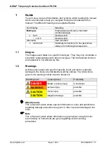
Page 9: ...chematic representation with other hoist types The fundamental function and operation is not affected by this 1 2 Warnings Activities associated with specific hazards to life and limb or potential dam...

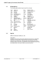
Page 10: ...etres per hour mph miles per hour inc including if nec if necessary i e id est that is reg regarding RH relative humidity approx approximately diameter registered trademark copyright TM trademark per...

Page 11: ...2389 9874 33 GEDA Dechentreiter GmbH Co KG East Ernst M Jahr Strasse 5 07552 Gera Tel 49 0 365 55280 0 Fax 49 0 365 55280 29 USA Subsidiary Russia Subsidiary GEDA USA LLC 1151 Butler Road USA 77573 L...

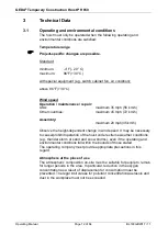
Page 12: ...embly maximum 28 mph 45 km h Observe the height dependent change in wind speed It may be necessary to cease prohibit operation of the hoist under extreme weather conditions e g thunder storm or sand a...

Page 13: ...ox 48 m min Approx 78 m min Approx 108 m min Approx 157 ft min Approx 256 ft min Approx 354 ft min Gravitational acceleration in the car with EMERGENCY OFF 1 g 3 3 Drive Technical information about th...

Page 14: ...l and the use of non approved spare parts releases the manufacturer from any liability 4 2 Hoist limitations The hoists must only be used in compliance with the technical data features the max permiss...

Page 15: ...regulations that must be complied with by the operating company all other information in this manual It is prohibited to start up or operate the hoists without having read the manual beforehand The m...

Page 16: ...ointed and sharp edged parts Drives Chains ropes cables Energies Electricity Hot surfaces Potential energy raised components tipping falling loads falling tools Operating materials Oils Greases Emerge...

Page 17: ...he warranty 4 13 GEDA training sessions GEDA offers detailed training sessions in order to enable the highest degree of safety and economic efficiency when operating the elevator Please contact the GE...

Page 18: ...ity and responsibility of the respective group of people Safety conscious conduct avoiding hazards Conduct in an emergency Application of the emergency evacuation plan Correct hoist operation The mean...

Page 19: ...3 Checking correct and proper condition and use At regular intervals the operating company must take appropriate measures to check that the hoist is being used according to the intended use that the h...

Page 20: ...must be informed by the operating company about obligatory safety regulations valid accident prevention guidelines as well as the hoist s functions and safety equipment The corresponding instructions...

Page 21: ...may occur during operation of start up of the hoist All persons must comply with the instructions of the hoist operator 6 3 Specialists for servicing maintenance assembly A person who on account of h...

Page 22: ...mergency equipment may neither be removed altered nor made ineffective and must be inspected at regular intervals to ensure function and completeness Rectify any faults which fall within your area of...

Page 23: ...bility of the electrical components must be inspected at regular intervals and if necessary replaced The generation accumulation of explosive fine particulate matter must be prevented removed immediat...

Page 24: ...ded use and within the specifications of their technical data Test the parts to ensure that they are functioning correctly after the work Make sure that no hazards will arise as a result of the hoist...

Page 25: ...d Do not touch sockets cables or electrical components with wet or damp hands Cleaning tasks on live components must only be carried out by qualified electrical personnel 7 6 Conduct in an emergency O...

Page 26: ...ing level safety doors The operating company is solely responsible for installing and operating the landing level safety doors Before initial use the operating company must ensure that the landing lev...

Page 27: ...t Before performing the special test temperatures must be above 4 F 20 C for a minimum of 3 hours Clear ice and snow from the hoist Switch on the master switch green light comes on Press all EMERGENCY...

Page 28: ...as far as the layer of snow Hoist could be damaged Storms lightening hail Injury to people as a result of lightening or hail Damage to the hoist as a result of strong gusts of wind bolts of lightening...

Page 29: ...ever remain inside the enclosure during operation When working inside the enclosure switch off the main switch and secure against switching on 8 3 Fall from the ladder DANGER Danger to life Fall from...

Page 30: ...ents must only be carried out by qualified electrical personnel Wear personal protective equipment 8 7 Reaching into the travel path during operation DANGER Danger to life Crushing or amputation of li...

Page 31: ...here is an impact hazard 8 12 Suspended loads WARNING Danger to life Raised load Do not stand under suspended loads Do not stand on a suspended load Only lift loads at the suspension points Only use s...

Page 32: ...e 1 The bottom stop position is provided with an enclosure The enclosure prevents access to the bottom hazard area The car can only be accessed through the landing level safety gate and door to the ca...

Page 33: ...nd servicing Make sure that no one is on the roof of the car or inside the enclosure Always carry out visual inspections before function checks Operation is prohibited until the defects are rectified...

Page 34: ...aks Run car to its maximum height Stop the car at the upper EMERGENCY LIMIT approach bar Travel further upwards not possible Run car down to ground station Stop the car at the ground station Travel fu...

Page 35: ...eam jet equipment high pressure cleaners Electrical components could be damaged Do not touch sockets cables or electrical components with wet or damp hands Cleaning tasks on live components must only...

Page 36: ...top at next landing level 6 UP button 7 DOWN button 8 STOP button stop at the current position 10 3 1 1 Operation Ascend Press the UP button Descend Press the DOWN button Stop Next Landing Stop at the...

Page 37: ...Key field 0 9 Landing level selection Start button No function 5 Stop Next Landing SNL Stop at next landing level only when landing approach bar is installed Illuminated when operated Press and hold E...

Page 38: ...Car stops at the next landing level Travel is then continued to the target landing using the keypad 10 3 3 Control in the car Joystick with 5 switching positions 1 Car emergency lighting 2 Control li...

Page 39: ...d Move Joystick downwards First switching position Car moves slowly Second switching position Car moves fast Stop car Move Joystick to centre position In an emergency by activating the EMERGENCY STOP...

Page 40: ...Overload warning light 4 Stop Next Landing SNL Stop at next landing level only when landing approach bar is installed Illuminated when operated Press and hold EMERGENCY DOWN button after approx 30 se...

Page 41: ...n Stop Next Landing illuminates Car stops at the next landing below 10 3 5 Ground station switch box For joystick control in the car 1 Main switch Switches the hoist on or off at the beginning end of...

Page 42: ...anding SNL Stop at next landing level The supply line 7 7 pole plug red from the first landing level door switch box is plugged into the ground station at the switch box If there are several levels wi...

Page 43: ...es states in which the standards ANSI A10 4 and AS 1418 7 are applicable For hoists with an operating speed of more than 42 m min Opening from the inside Carefully open or close the door in the centre...

Page 44: ...n etc by personnel authorised to do so 10 4 1 Drop test control Used to test the safety gear with a drop test The drop test control unit must be kept locked up by the operating company 1 EMERGENCY STO...

Page 45: ...or Dummy plug in normal mode assembly control drop test control Example Assembly mode Assembly control is plugged and hold the button 10 seconds in this position 20 minutes permanent lubrication Assem...

Page 46: ...mergency The hoist has 5 EMERGENCY STOP buttons Car control unit Car roof maintenance control Ground station switch box Drop test control Assembly control Triggering an EMERGENCY STOP hoist shut down...

Page 47: ...n the hoist immediately if the door lock is defective DANGER Danger to life Car creates a crush hazard Never remain inside the enclosure during operation When working inside the enclosure switch off t...

Page 48: ...11 5 EMERGENCY limit switches The EMERGENCY limit switch stops the car at the top or bottom end position This prevents the car from moving past the top end position for example 11 6 Locks to prevent u...

Page 49: ...rench to unlock the trapdoor in the roof Equipment for adjusting the track rollers 2 x open end spanner AF 50 46 Equipment for resetting the safety gear 1 x Ring spanner AF 55 1 x Hexagonal offset scr...

Page 50: ...ssembly tasks or to evacuate people DANGER Danger to life Fall from the ladder Only one person allowed on the ladder at a time Always hold on with at least one hand Always face the ladder to ascend an...

Page 51: ...ndible ladder 1A from the ladder until it engages Take the triangular wrench from the document and tool box in the car and place it on the triangular bolt of the roof lock 3 Unlock the lock 3 by turni...

Page 52: ...650 Operating Manual Page 52 of 64 BL148GB2017 11 Open the roof hatch 4 and if necessary secure it against shutting using appropriate measures e g by a strong wind A bar 5 is installed to ensure safe...

Page 53: ...y lowering too quickly This disables the car which must then be subsequently enabled Only lower the car very slowly The drives are located on the roof of the car Remove the extensions 1 for the brake...

Page 54: ...ities must also be notified fire brigade technical support factory security office 12 1 Basic conduct in the event of a rescue malfunction Remain calm and do not act hastily Get an overview of the sit...

Page 55: ...ng will explain the individual measures of the plan 12 3 Rescuing persons from the car Action 1 Self rescue with a reference run Press and hold the yellow button 1 after approx 30 seconds the car move...

Page 56: ...on the electrical installation of the construction hoist switch off and lock the main switch For safety disconnect the mains plug 13 1 Display module The display module indicates the direction of tra...

Page 57: ...17 Assembly bridge Roof 2 extended ERROR 20 EMERGENCY STOP ground station ERROR 21 EMERGENCY STOP car control ERROR 22 EMERGENCY STOP roof switch box ERROR 23 Assembly drop test control active ERROR 2...

Page 58: ...n Trapdoor open EMERGENCY limit switch has activated Locking bolts of the assembly crane are not removed Safety gear engaged Unlock EMERGENCY STOP button Close sliding door of car Close enclosure Clos...

Page 59: ...st is moving in reduced speed Deficiency of grease in the lubrication device more than 4 operating hours Check Change grease cartridge 13 2 1 Motor is not producing full output Voltage drop of more th...

Page 60: ...arge o the sensing device is defective o there is a fault in the electrical system o the car is overloaded overload protection o the car was lowered with the manual brake release Measures Connect the...

Page 61: ...e During travel the assembly crane must not swing into the path of travel mast Thus this must be locked in a secure position The locking bolts 1 removed interrupt the safety circuit and the car will n...

Page 62: ...parts guarantee full function as well as safety and reliability The use of non approved spare parts releases GEDA from any liability for damage arising as a consequence of any such use When ordering s...

Page 63: ......

Page 64: ...GEDA Dechentreiter GmbH Co KG Mertinger Strasse 60 86663 Asbach B umenheim Tel 49 0 9 06 98 09 0 Fax 49 0 9 06 98 09 50 E Mail info geda de Web www geda de BL148 GB Edition 11 2017...

Reviews: