background image


LTE CPE


Quick installation Guide 


Summary of Contents for WLTMS-110_384041

Page 1: ...LTE CPE Quick installation Guide ...

Page 2: ...WLTMS 110_384041 Connection Guide ...

Page 3: ...o Ltd Notice Gemtek reserves the right to change specifications without prior notice While the information in this document has been compiled with great care it may not be deemed an assurance of product characteristics Gemtek shall be liable only to the degree specified in the terms of sale and delivery The reproduction and distribution of the documentation and software supplied with this product ...

Page 4: ...Connectors 1 One RJ 45 connector for connecting to the PoE adaptor 2 LED indicator inside and SIM card slot for inserting SIM card 3 A grounding screw on the rear panel ...

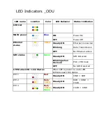
Page 5: ...Ethernet Connected Blinking Data Transmission OFF No Ethernet action SIM status Green Steady ON SIM Detected Blinking when On hook PUK PIN Code OFF No SIM Detected LTE Status LED Link Status When CPE is power on each LED indicates each link status LTE 1 Red Steady ON CINR 8dB LTE 2 Red Yellow Steady ON 8dB CINR 15dB LTE 3 Red Yellow Green Steady ON 15dB CINR ...

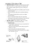
Page 6: ...ny metallic reflective surfaces Be sure to ground LTE Outdoor CPE with an appropriate grounding wire not included by attaching it to the grounding screw on the unit and to a good ground connection Mounting the ODU Mount LTE Outdoor CPE on a 1 4 pole using the supplied kit or the optional tilt accessory Using the clamp 1 Thread the M10 100mm bolt through a spring washer flat washer and the bracket ...

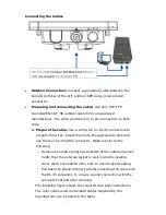
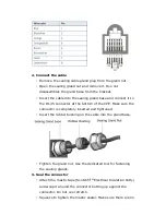
Page 7: ...nsert them into the appropriate pins and use the tool to crimp the connector Make sure to do the following Remove as small a length as possible of the external jacket Verify that the external jacket is well inside the sealing cover when connected to the unit to ensure good sealing Pull back the shield drain wire before inserting the cable into the RJ 45 connector to ensure a good connection with t...

Page 8: ... at the bottom of the CPE Make sure the connector is completely inserted and tightened Insert the rubber bushing on the cable into the gland base Tighten the gland nut Use the dedicated tool for fastening the sealing glands 3 Seal the connector Attach the mastic tape ScotchfilTM Electrical Insulation Putty and wrap it around the connector butting up against the connector Do not over stretch Squeez...

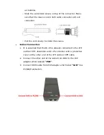
Page 9: ...rink the sleeve Indoor Connection 1 It is assumed that the RJ 45 is already connected to the LTE outdoor CPE Assemble an RJ 45 connector with a protective cover on the other end of the LTE outdoor CPE cable 2 Connect the other end of the cable from ODU to the PoE adaptor which labeled POE 3 Connect RJ45 cable from PoE adaptor which label LAN to a PC NB Hub Switch ...

Page 10: ...rface Step1 Open the Web browser Internet Explorer and enter the default IP address of the ODU CPE which is http 192 168 15 1 Web browser Step2 Enter ODU administrator login username password to access the web management interface The default username password is administrator administrator ...

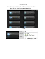
Page 11: ...nterface Step3 The page shown here gets displayed in your browser after login you can now configure the device settings GUI Interface Mode LTE Operator APN Name Signal More bar means better signal Disconnect no signal ...

Page 12: ...articular installation If this equipment does cause harmful interference to radio or television reception which can be determined by turning the equipment off and on the user is encouraged to try to correct the interference by one of the following measures Reorient or relocate the receiving antenna Increase the separation between the equipment and receiver Connect the equipment into an outlet on a...

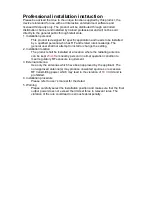
Page 13: ...hall not attempt to install or change the setting 2 Installation location The product shall be installed at a location where the radiating antenna can be kept 23cm from nearby person in normal operation condition to meet regulatory RF exposure requirement 3 External antenna Use only the antennas which have been approved by the applicant The non approved antenna s may produce unwanted spurious or e...

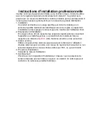
Page 14: ...par l utilisateur final 2 Emplacement d installation En usage normal afin de respecter les exigences reglementaires concernant l exposition aux radiofrequences ce produit doit etre installe de facon a respecter une distance de 23cm entre l antenne emettrice et les personnes 3 Antenn externe Utiliser uniiquement les antennes approuvees par le fabricant L utilisation d autres antennes peut conduire ...

Reviews: