background image

Owner’s Manual

50 Hz Air-Cooled Generators

8 / 10 / 13 kVA

SAVE THIS MANUAL FOR FUTURE REFERENCE


This manual must be used in conjunction with the appropriate Installation Manual.

Register your Generac product at:

WWW.GENERAC.COM

1-888-GENERAC
(1-888-436-3722)

Para español , visita: 

http://www.generac.com/service-support/product-support-lookup

Найти


версию


на


русском


языке

:  

http://www.generac.com/service-support/product-support-lookup

000918

(000209a)

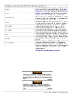
WARNING

This product is not intended to be used in  
a critical life support application. Failure to  
adhere to this warning could result in  
death or serious injury.

Summary of Contents for 10 kVA

Page 1: ...oduct at WWW GENERAC COM 1 888 GENERAC 1 888 436 3722 Para español visita http www generac com service support product support lookup Найти версию на русском языке http www generac com service support product support lookup 000918 000209a WARNING This product is not intended to be used in a critical life support application Failure to adhere to this warning could result in death or serious injury ...

Page 2: ... checked periodically by an Independent Authorized Service Dealer Normal maintenance service and replacement of parts are the responsibility of the owner operator and as such are not considered defects in materials or workmanship within the terms of the warranty Individual operating habits and usage may contribute to the need for additional maintenance or service When the generator requires servic...

Page 3: ...face Menu Displays 11 The LCD Display 11 Menu System Navigation 11 Battery Charger 14 Manual Transfer Operation 14 Transfer to Generator Power Source 14 Transfer Back to Utility Power Source 15 Automatic Transfer Operation 15 Automatic Sequence of Operation 15 Utility Failure 15 Cranking 15 Cold Smart Start 15 Load Transfer 15 Shutting Generator Down While Under Load 16 Section 4 Maintenance Perfo...

Page 4: ...Table of Contents iv Owner s Manual for 50 Hz Air cooled Generators This page intentionally left blank ...

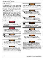
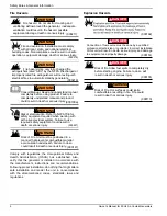
Page 5: ...lly Their definitions are as follows NOTE Notes provide additional information important to a procedure or component These safety warnings cannot eliminate the hazards they indicate Observing safety precautions and strict compliance with the special instructions while performing the action or service are essential to preventing accidents The operator is responsible for proper and safe use of the e...

Page 6: ...s injury 000191 DANGER 000187 WARNING 000130 WARNING Accidental Start up Disconnect the negative battery cable then the positive battery cable when working on unit Failure to do so could result in death or serious injury 000182 WARNING 000155 WARNING Only a trained and licensed electrician should perform wiring and connections to unit Failure to follow proper installation requirements could result...

Page 7: ... 000144 DANGER Electrocution Contact with bare wires terminals and connections while generator is running will result in death or serious injury 000150 DANGER Electrocution Never connect this unit to the electrical system of any building unless a licensed electrician has installed an approved transfer switch Failure to do so will result in death or serious injury 000131a DANGER Electrical backfeed...

Page 8: ...charged or improperly rated fire extinguishers will not extinguish electrical fires in automatic standby generators 000100a WARNING Consult Manual Read and understand manual completely before using product Failure to completely understand manual and product could result in death or serious injury WARNING required safety equipment could result in death or serious injury 000221 Risk of electrocution...

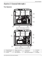
Page 9: ...0 Engine 8 kVA Unit Figure 2 2 GT 990 Engine 10 13 kVA Units A Exhaust Enclosure D Battery Compartment G Circuit Breakers J Oil Fill Cap B Composite Base E Fuel Regulator H Control Panel K Air Filter C Oil Filter F Fuel Inlet Back I Data Label See Sample L Oil Dipstick 000701 A L B C D E F G H K J I 000901 A B L C D E K F G H J I ...

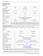
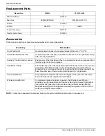
Page 10: ...s section These generators are rated in accordance with UL 2200 Safety Standard for Stationary Engine Generator Assemblies and CSA C22 2 No 100 04 Standard for Motors and Generators Natural Gas ratings will depend on specific fuel BTU joules content Typical derates are between 10 20 off the LP gas rating Circuits to be moved must be protected by same size breaker For example a 15 amp circuit in th...

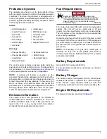
Page 11: ...he engine has been fitted with a dual fuel carburetion system The unit will run on natural gas or LP gas vapor but it has been factory set to run on natural gas The fuel system will be configured for the available fuel source during installation Recommended fuels should have a BTU joules content of at least 1000 BTUs per cubic foot 37 26 megajoules per cubic meter for natural gas or at least 2500 ...

Page 12: ...ckout Enables any of the transfer switches to completely lock out one large electrical load by tying into its control system Fascia Base Wrap The fascia base wrap snaps together around the bottom of the new air cooled generators This offers a sleek contoured appearance as well as offering protection from rodents and insects by covering the lifting holes located in the base Requires use of the moun...

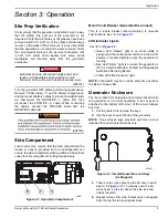
Page 13: ...Generator Disconnect This is a 2 pole breaker rated according to relevant specifications See A in Figure 3 1 LED Indicator Lights See B in Figure 3 1 Green LED Ready light is on when utility is present and the control panel button is in the AUTO position This also indicates when the generator is running Red LED Alarm light is on when the generator is OFF or a fault is detected Contact an Independe...

Page 14: ...re performing any maintenance on the generator set to OFF remove 7 5 Amp fuse T1 and T2 battery charge fuses and disconnect battery cables to prevent accidental start up Disconnect the cable from the battery post indicated by a NEGATIVE NEG or first then remove the POSITIVE POS or cable When reconnecting the cables connect the POSITIVE cable first the NEGATIVE cable last NOTE The enclosed keys pro...

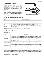
Page 15: ...is button activates fully automatic system operation It also allows the unit to automatically start and exercise the generator according to the exercise timer see Battery Charger Off This button shuts down the engine and also prevents automatic operation of the unit Manual This button will crank and start the generator Transfer to standby power will not occur unless there is a utility failure Feat...

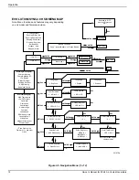
Page 16: ...se Set Error USB Warning Download Failure Running Manual Running Utility Lost Running Remote Start Running 2 Wire Start Running Exercise Switched Off Stopped Auto Stopped Alarm Alarm Message s High Temperature Low Oil Pressure Overcrank Overspeed Overvoltage Undervoltage Overload Underspeed RPM Sensor Loss Controller Fault Wiring Error Stepper Overcurrent Fuse Problem ESC Select Min 0 59 0 ESC ESC...

Page 17: ...vice Current V XXXX USB V XXXX Are You Sure Yes or No ESC ENTER ESC ENTER ESC ENTER Select Yes then Press Enter to continue or Press ESCAPE to escape out of updating During update process the Blue Manual light flashes then the Green Auto light flashes Sequence does this twice When update is complete the unit returns to Install Wizard menu When the controller powers up the very first screen display...

Page 18: ...o ON or CLOSED The standby power source now powers the loads Figure 3 7 Manual Transfer Switch Operation 000132 DANGER Electrocution Do not manually transfer under load Disconnect transfer switch from all power sources prior to manual transfer Failure to do so will result in death or serious injury and equipment damage 000228 A B MANUAL Will not transfer to generator if utility is present Will tra...

Page 19: ...lity power is restored above 80 nominal at any time from the initiation of the engine start until the generator is ready to accept load five second warm up time has not elapsed the controller will complete the start cycle and run the generator through its normal cool down cycle however the load will remain on the utility source Cranking The system will control the cyclic cranking as follows Five c...

Page 20: ...UTO and online 1 Turn the main utility disconnect OFF 2 Turn the main line circuit breaker MLCB on the generator to OFF OPEN 3 Turn the generator OFF To turn the generator back ON 1 Put the generator back into AUTO and allow to start and warm up for a few minutes 2 Set the MLCB on the generator to ON The system will now be operating in automatic mode The main utility disconnect can be turned ON CL...

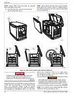
Page 21: ...ppear on the control panel display at any one time Once the first alert is cleared the next active alert will be displayed Before Servicing Follow the steps below prior to inspecting maintaining or servicing this unit 1 Allow the generator to cool thoroughly before removing battery connections for maintenance or other service 2 Unlock left and right side locks Open lid NOTE For best results press ...

Page 22: ...ck Gap Replace Spark Plugs Inspect Adjust Valve Clearance Contact the nearest independent Independent Authorized Service Dealer for assistance if necessary Remove any shrubs or tall grasses which have grown within 3 ft 0 91m of the intake and discharge louvers on the sides of the enclosure Clean any debris dirt grass clippings etc which have accumulated inside the enclosure Verify that all sources...

Page 23: ...vice Class SJ SL or better Use no special additives Select the appropriate viscosity oil grade according to the expected operating temperature Synthetic oil also can be used in the appropriate weight as standard Figure 4 1 Recommended Oil Based on Temperature SAE 30 above 32 F 0 ºC SAE 10W 30 between 40 º and 10 ºF 4 º and 23 ºC Synthetic SAE 5W 30 for all temperature ranges Changing the Oil and O...

Page 24: ...r cover and cover clips Spark Plugs Reset the spark plug s gap or replace the spark plug s as necessary 1 With the generator shut down lift the lid and remove the front panel 2 Clean the area around the base of the spark plug s to keep dirt and debris out of the engine 3 Remove the spark plug s and check the condition Install a new plug s if the old plug is worn or if reuse is questionable 4 Clean...

Page 25: ...necessary Battery Maintenance The battery should be regularly inspected per the Service Schedule 1 With the generator shut down lift the lid and remove the front panel 2 Inspect the battery posts and cables for tightness and corrosion Tighten and clean as necessary 3 Check the battery fluid level of unsealed batteries and if necessary fill with distilled water only DO NOT use tap water Also have t...

Page 26: ...set the generator main circuit breaker Generator Disconnect to OFF OPEN 4 Turn off the utility power to the transfer switch 5 Remove the 7 5 Amp fuse from the generator s control panel 6 Disconnect the battery cables Remove negative cable first 7 Remove battery charger AC input T1 Neutral cable has white sleeve at controller 8 While the engine is still warm drain the oil completely and then refill...

Page 27: ...n wrong position 1 Check replace air cleaner 2 Clean or replace spark plug 3 Confirm fuel pressure to regulator is 10 12 in water column 19 22 mm mercury for LP and 3 5 7 in water column 9 13 mm mercury for natural gas 4 Turn fuel conversion valve to correct position Generator is set to OFF but the engine continues to run 1 Controller wired incorrectly 2 Defective control board 1 2 No AC output fr...

Page 28: ...in AUTO with utility loss Check the LEDs Screen for alarms Check oil level add oil see Checking Engine Oil Level If oil level is correct contact an Independent Authorized Servicing Dealer RPM SENSE LOSS RED Unit will not start in AUTO with utility loss Check the LEDs Screen for alarms Clear alarm Using the control panel check the battery by navigating to the BATTERY MENU option from the MAIN MENU ...

Page 29: ...ery by navigating to the BATTERY MENU option from the MAIN MENU If it states battery is GOOD contact an Independent Authorized Servicing Dealer If it states CHECK BATTERY replace the battery BATTERY PROBLEM YELLOW Yellow LED illuminated in any state Check the screen for additional information Contact an Independent Authorized Servicing Dealer CHARGER WARNING YELLOW Yellow LED illuminated in any st...

Page 30: ...Troubleshooting Quick Reference Guide 26 Owner s Manual for 50 Hz Air Cooled Generators This page intentionally left blank ...

Page 31: ......

Page 32: ...nc All rights reserved Specifications are subject to change without notice No reproduction allowed in any form without prior written consent from Generac Power Systems Inc Generac Power Systems Inc S45 W29290 Hwy 59 Waukesha WI 53189 1 888 GENERAC 1 888 436 3722 generac com ...

Reviews: