background image


OPERATOR’S MANUAL 

Safety, Operation & Service Information  


    RIP-R-STRIPPER Self-Propelled Floor Covering Stripper  

Model: 

FCS18 

Form:  

GOM19061901US, Version 1.0, Original Instructions 


Do not discard this manual.   


Keep manual readily available for reference during operation or when servicing product. 


Before operation, read and comprehend operator manual content. 


Customer Service:  

001 507 451 5510


Customer Service Telefax:  

001 507 451 5511


                Note: There is no charge for Customer Service. 


Internet Address:  

http://www.generalequip.com


Email:  

general@generalequip.com


Mailing Address:


General Equipment Company, 620 Alexander Dr. S.W., P.O. Box 334, Owatonna, MN 55060, USA 


Copyright 2019, General Equipment Company, All rights reserved.


Summary of Contents for FCS18

Page 1: ...g operation or when servicing product Before operation read and comprehend operator manual content Customer Service 001 507 451 5510 Customer Service Telefax 001 507 451 5511 Note There is no charge for Customer Service Internet Address http www generalequip com Email general generalequip com Mailing Address General Equipment Company 620 Alexander Dr S W P O Box 334 Owatonna MN 55060 USA Copyright...

Page 2: ...overing construction CAUTION The concept of electrically powered walk behind floor covering removal equipment has been successfully utilized for many years as a practical solution to many types of floor covering removal requirements The basic concept is proven and well accepted within the associated marketplaces Use of a RIP R STRIPPER requires strenuous work activity This type of work activity ca...

Page 3: ..._____________________ Owner Instructor __________ Date _________________________________ Operator ______________________________ Owner Instructor __________ Date _________________________________ Operator ______________________________ Owner Instructor __________ Date _________________________________ Operator ______________________________ Owner Instructor __________ Date ________________________...

Page 4: ...structional operation requirements applicable OSHA requirements local laws and regulations job site safety plus RIP R STRIPPER maintenance Constantly examine and upgrade program to guarantee owner s and or operator s safety Each operator must be fully instructed regarding specifics of this safety program 4 SAFETY SYMBOLS SAFETY ALERT SYMBOL SIGNAL WORDS The safety alert general warning symbol indi...

Page 5: ... the RIP R STRIPPER as demanded by specific job applications When lifting two people are required Utilize proper lifting techniques to minimize fatigue and back related injuries Back Anatomy The human body is supported by the spinal column consisting of thirty bones called vertebrae all linked and supported by a series of muscles Pads called discs separate each vertebrae acting as cushions to pres...

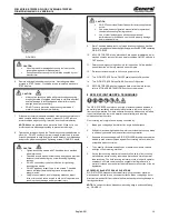
Page 6: ...ve a DO NOT allow operator handle and main frame to make direct contact with each other while transporting Provide proper protection between RIP R STRIPPER components and vehicle b DO NOT drop unit directly against exciter plate Provide support block under main frame to prevent direct contact and or damage to exciter plate and related components 7 All equipment must be secured in on vehicles with ...

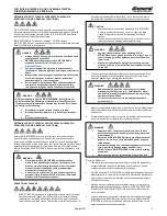
Page 7: ...ctive materials by industry approved and or accepted practice BEFORE removing floor covering Determine RIP R STRIPPER is properly grounded and extension cords are free of cuts Abrasions and or exposed cable strands DANGER Always assume flooring removal location contains buried underground obstructions BEFORE attempting to operate RIP R STRIPPER in proposed location s call 811 and or visit www Call...

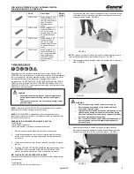
Page 8: ...overheat and can cause unrepairable damage to motor and related controls An improperly grounded circuit increases risk of electric shock A qualified electrician may need to be consulted IMPORTANT Operating RIP R STRIPPER with improper voltage and or amperage will result in unrepairable damage to electric motor and related controls 7 STANDARD PRODUCT ACCESSORIES Refer to FIGURE 5 for overview descr...

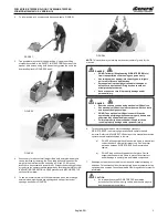
Page 9: ...ve lid of crate surrounding the base portion of the unit plus the screws holding the crossbars positioned inside crate 3 Using hammer and or pry bar carefully separate crate sides to expose the unit 4 Following PROPER LIFTING PROCEDURES and handling steps under TRANSPORTATION in the BEFORE OPERATING section of this manual remove the base portion of the unit from the crate base INSTALLING ADJUSTING...

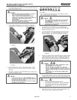
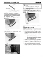
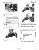
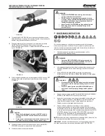
Page 10: ...sting blade is present in machine reinstall protective edge covering if originally supplied with blade to prevent injury and protect blade edge 5 Using T handle wrench loosen cap screws securing blade clamp DO NOT fully remove screws or blade clamp FIGURE 12 DANGER Wear appropriate safety glasses and other appropriate safety apparel when installing or removing blade on RIP R STRIPPER Improper cont...

Page 11: ...ring material 3 Adequate force exerted against RIP R STRIPPER by self propelled drive wheels to push accessory blade against floor covering material to deliver acceptable productivity rates 4 Type density thickness and adhesion of adhesives mastics thinsets and type of floor covering material 5 No two floor covering materials are exactly alike no two floor covering materials can be removed by exac...

Page 12: ...develop standardized RIP R STRIPPER removal techniques and will require trial and error until satisfactory results are achieved Experience gained over time along with common sense will help minimize the amount of necessary testing 1 Specific type and or density of adhesives mastics and thinset materials that bond floor coverings to work surface plus variety of floor covering materials and jobsite ...

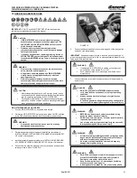
Page 13: ...n contain a fault A fault can generate a dangerous operating configuration that can result in property damage and or personal injury WARNING DO NOT abuse the power cord Never use power cord to move RIP R STRIPPER or pull plug from receptacle Damage to cord and or machine can result Keep cord away from heat oil sharp edges including accessory tool or moving parts A damaged cord increases the risk o...

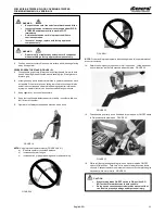
Page 14: ...21 NOTE Proper and improper operator stances depicted in this operator manual are not all inclusive 14 Determine emergency stop button is in full up position Yellow band near bottom of button will be fully exposed when complete FIGURE 22 FIGURE 22 15 Grasp handle grip firmly in one hand and turn main power ON OFF switch to ON position with other hand FIGURE 23 FIGURE 23 16 While still firmly grasp...

Page 15: ...aper clearance to minimize build up on wheels Refer to MAINTENANCE INSTRUCTIONS section of this manual for more information STOPPING RIP R STRIPPER 21 In emergency situations only such as an extension cord becoming entangled about RIP R STRIPPER and or operator firmly hit emergency stop button Entire unit will shut off when activated FIGURE 28 WARNING Properly dispose of all accumulated floor cove...

Page 16: ...individual parts operator controls and safety devices for proper function Tighten fasteners as necessary Replace any worn or damaged part or assembly 6 Remove all loose material accumulations dirt and grease on internal external surfaces to prevent safety hazards poor performance and reduced service life Use proper dust collection system as necessary to remove most accumulation then use safety typ...

Page 17: ...IPPER NOTE Ball bearings for RIP R STRIPPER are shielded or sealed and will not require lubrication during normal service life ACCESSORY BLADE SHARPENING 1 Blades can be sharpened using a file designed for use on metal materials This method will not duplicate original blade sharpening process but can significantly increase overall productivity rates versus use of a dull blade a Remove blade from R...

Page 18: ...Replace blade Worn or damaged elastomeric mounts Replace mounts UNEVEN ACCESSORY BLADE WEAR Possible Cause Correction Incorrect blade installation See INSTALLING REMOVING ACCESSORY BLADES this manual Damaged exciter plate Replace plate Damaged elastomeric rubber mount s Replace mounts Bent blade Replace blade EXCESSIVE JUMPIING ON WORK SURFACE Possible Cause Correction Incorrect blade installation...

Page 19: ...FCS18 RIP R STRIPPER FLOOR COVERING STRIPPER FORM GOM19061901US VERSION 1 0 English EN 18 ...

Page 20: ...FCS18 RIP R STRIPPER FLOOR COVERING STRIPPER FORM GOM19061901US VERSION 1 0 English EN 19 ...

Page 21: ...FCS18 RIP R STRIPPER FLOOR COVERING STRIPPER FORM GOM19061901US VERSION 1 0 English EN 20 ...

Page 22: ...FCS18 RIP R STRIPPER FLOOR COVERING STRIPPER FORM GOM19061901US VERSION 1 0 English EN 21 ...

Page 23: ...FCS18 RIP R STRIPPER FLOOR COVERING STRIPPER FORM GOM19061901US VERSION 1 0 English EN 22 ...

Page 24: ...FCS18 RIP R STRIPPER FLOOR COVERING STRIPPER FORM GOM19061901US VERSION 1 0 English EN 23 ...

Page 25: ...FCS18 RIP R STRIPPER FLOOR COVERING STRIPPER FORM GOM19061901US VERSION 1 0 English EN 24 ...

Page 26: ...FCS18 RIP R STRIPPER FLOOR COVERING STRIPPER FORM GOM19061901US VERSION 1 0 English EN 25 ...

Page 27: ...FCS18 RIP R STRIPPER FLOOR COVERING STRIPPER FORM GOM19061901US VERSION 1 0 English EN 26 ...

Page 28: ...FCS18 RIP R STRIPPER FLOOR COVERING STRIPPER FORM GOM19061901US VERSION 1 0 English EN 27 ...

Page 29: ...FCS18 RIP R STRIPPER FLOOR COVERING STRIPPER FORM GOM19061901US VERSION 1 0 English EN 28 ...

Reviews: