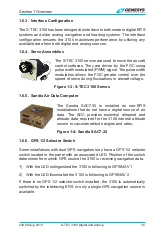
background image

S-TEC 3100 Digital and Analog 

Flight Control System

S-TEC 3100

Digital and Analog  

Flight Control System

Pilot Guide

PRECISE PERFORMANCE.  

P R O V E N   E X P E R I E N C E .  

PERSONALIZED ATTENTION.

Summary of Contents for S-TEC 3100

Page 1: ...S TEC 3100 Digital and Analog Flight Control System S TEC 3100 Digital and Analog Flight Control System Pilot Guide PRECISE PERFORMANCE PROVEN EXPERIENCE PERSONALIZED ATTENTION...

Page 2: ...ts limitations and emergency procedures 2019 Genesys Aerosystems All Rights Reserved Information contained in this document is subject to change without notice No part of this document may be reproduc...

Page 3: ...g 2019 S TEC 3100 Digital and Analog ii Revision Record Retain this record in front of guide Revision Number Revision Date Notes Pages changed added or deleted by current revision 1st Ed February 2018...

Page 4: ...lector Switch 1 5 1 7 Interfaced Avionics 1 6 1 7 1 Garmin G500 G600 TXi EFIS 1 6 1 7 2 Aspen EFD 500 1000 MAX 1 6 1 7 3 Avidyne EXP5000 and Meggitt EFIS 1 7 1 7 4 Analog DG HSI 1 7 1 8 Display Legend...

Page 5: ...re Select Manual Altitude Capture 3 17 3 8 5 2 S TEC 3100 Internal Altitude Pre Select 3 18 3 8 5 3 S TEC ST 360 Altitude Selector Alerter 3 19 3 8 5 4 Garmin G500 G600 TXi Pre Select 3 19 3 9 Additio...

Page 6: ...9 Pitch Attitude PITCH Mode 3 14 Figure 3 10 Indicated Airspeed IAS Mode 3 15 Figure 3 11 Vertical Speed VS Mode 3 15 Figure 3 12 Altitude Hold ALT HOLD Mode 3 16 Figure 3 13 Altitude Pre Select 3 16...

Page 7: ...directly proportional to the pilot s knowledge of its operating procedures Therefore it is highly recommended that the pilot develop a thorough understanding of the 3100 its modes and operating proce...

Page 8: ...if enabled 1 4 LIMITATIONS 1 4 1 Altitude Pre Select Limitations The S TEC 3100 relies on digital air data information for altitude pre select Some configurations may not have altitude pre select if t...

Page 9: ...VL Mode Returns aircraft to level flight and a configured pitch angle for the aircraft refer to AFMS for pitch angle value Indicated Airspeed IAS Mode Holds indicated airspeed Vertical Speed VS Mode H...

Page 10: ...tion may be controlled through the front panel The S TEC 3100 has an on board MEMS device that calculates attitude angles and rates in the pitch roll and yaw axis This may be configured to act as the...

Page 11: ...3 S TEC 3100 Servos 1 6 5 Sandia Air Data Computer The Sandia SAC7 35 is installed on non EFIS installations that do not have a digital source of air data The ADC provides essential airspeed and alti...

Page 12: ...d the 3100 reads VS IAS and ALT targets set on the EFIS display 3 8 5 If a target is set using the 3100 bezel directly this supersedes any existing targets from the EFIS and the new target is displaye...

Page 13: ...ors a GPS 1 2 selector switch is required See 1 6 6 for function details Flight director command bars are displayed on the EFIS 1 7 4 Analog DG HSI All mode annunciations are displayed on the 3100 bez...

Page 14: ...6 Approach APR Mode button 7 Level LVL Mode button 8 Ambient light sensor 9 Indicated Airspeed IAS Mode button 10 Vertical Speed VS Mode button 11 Altitude Hold ALT HOLD Mode button 12 Menu MNU Mode...

Page 15: ...ction both the AP master switch and trim master switch must be on during the 3100 self test CAUTION DO NOT taxi until initialization is complete and AP READY is displayed Taxiing during the initializa...

Page 16: ...tude sensor fails to align ATTITUDE FAIL appears If initial alignment is not valid after configured start up time or data becomes invalid following the alignment AP FAIL appears 2 2 PRE FLIGHT CHECKS...

Page 17: ...D ON Yaw servo is engaged Figure 3 1 Roll Attitude ROLL Mode During normal operation 1 Pressing always engages FD simultaneously 2 FD may be toggled ON OFF 3 YD may be toggled ON OFF independently 3 2...

Page 18: ...lateral movement required for the aircraft to follow the flight profile The flight profile is determined by the 3100 lateral and vertical mode selected and data from the interfaced avionics In FD mod...

Page 19: ...sive adverse yaw and coordinates turns Figure 3 2 Without Optional Yaw Damper Installed CAUTION YD mode should always be disengaged prior to takeoff and landing 3 6 ENVELOPE PROTECTION The 3100 protec...

Page 20: ...ft speed reaches the high speed limit which triggers an audible alarm followed by an Overspeed Overspeed voice alert Alerts continue until the aircraft speed is reduced below the overspeed recovery li...

Page 21: ...rspeed alert activates if the aircraft speed reaches the high speed limit which triggers an audible alarm followed by an Overspeed Overspeed voice alert The 3100 automatically commands the aircraft to...

Page 22: ...ed aircraft without the AP ICE SPEED option default to the higher underspeed protection limit as stated in the AFMS The AP ICE SPEED LED illuminates when the aircraft de icing system is engaged and in...

Page 23: ...the compass card Press to engage HDG The 3100 turns the aircraft onto the selected heading at a standard rate turn and holds it A new heading may be selected thereafter by setting the heading bug to...

Page 24: ...OR b Pilot Selectable Angle Set heading bug to desired intercept heading Press to engage HDG Press to arm NAV 4 If armed NAV automatically engages at the course capture point 5 Once captured the 3100...

Page 25: ...plan radial or the flight plan should be cleared to force the 3100 to use the DG HSI course input and prevent conflicting course information 3 7 3 2 GPS Steering NAVGPSS Mode 1 Program a valid waypoi...

Page 26: ...st be kept within the envelope speeds stated within the AFMS during coupled approaches Active envelope protection may deviate the aircraft from the glideslope path to remain within the airspeed envelo...

Page 27: ...nd selected course at a 45 angle OR b Heading Bug Vectors Set heading bug to desired intercept heading press to engage HDG Press to arm APR 4 If armed APR automatically engages and tracks the localize...

Page 28: ...nbound course 5 GS automatically arms and then captures once the aircraft is within dot 25 above or below the GS centerline During GS capture a VS descent proportional to the aircraft speed is establi...

Page 29: ...e manually selected for the 3100 to arm and track any vertical guidance Figure 3 8 RNAV Approach Procedure 1 Program approach into GPS navigator 2 Track the approach procedure using NAVGPSS mode APRGP...

Page 30: ...reverts to the armed vertical mode or PITCH mode if there is no armed vertical mode For example if the active mode is VS press to deselect HDG and engage PITCH Figure 3 9 Pitch Attitude PITCH Mode 3...

Page 31: ...d airspeed must be monitored when IAS mode is engaged since insufficient power at low airspeeds may cause the aircraft to stall and AP to disconnect Although the 3100 should limit the airspeed to 3 5...

Page 32: ...the altitude target does not change ALT HOLD mode The 3100 holds the aircraft at the captured altitude Press or to increase or decrease captured altitude A single press changes the altitude by 20 ft...

Page 33: ...ude Capture 2 S TEC 3100 Internal Altitude Pre Select 3 S TEC ST 360 Altitude Selector Alerter Pre Select 4 Garmin G500 600 TXi Pre Select 3 8 5 1 No Altitude Pre Select Manual Altitude Capture Figure...

Page 34: ...cancellation recall of the target altitude d Target altitude appears in units of feet for example 12500 2 Climb or descend in VS IAS or PITCH modes a VS mode VS target defaults to 500 fpm in the dire...

Page 35: ...st the IAS target with or to the desired speed c PITCH mode use CWS to establish desired climb or descent angle 3 8 5 4 Garmin G500 G600 TXi Pre Select Target altitude may be pre selected with the alt...

Page 36: ...AS mode Set the IAS target bug on the PFD if available For PFDs without an IAS bug the 3100 synchronizes to the current airspeed when IAS mode is engaged c PITCH mode Use CWS to establish desired clim...

Page 37: ...engages the flight director in go around mode with the steering bars are referenced to wings level and a pitch attitude specific to the aircraft type reference AFMS Figure 3 19 Go Around GA The AP may...

Page 38: ...t refer to AFMS for pitch angle value LVL mode may be engaged or disengaged at any time regardless of the roll axis or pitch axis mode Figure 3 20 Level Mode Roll and Pitch Hold Modes 3 9 4 1 Emergenc...

Page 39: ...tes when half bank is disengaged HB mode disengages either by pressing the switch again or if the 3100 mode is not HDG or GPSS mode Figure 3 22 HB Mode Switch Annunciator NOTE HB mode ONLY operates in...

Page 40: ...to be transmitted from the 3100 a flight test tool to inject failures using controller area network CAN messages and a variety of monitors to be disabled This mode is primarily intended to be used dur...

Page 41: ...he trim annunciation extinguishes 3 10 3 Manual Electric Trim The manual electric trim switch located on the control wheel stick can only be used to trim the aircraft when AP mode is disengaged Attemp...

Page 42: ...s 4 1 2nd Ed Aug 2019 S TEC 3100 Digital and Analog Section 4 Emergency Procedures Please refer to the aircraft AFMS for emergency procedures for Generator Failure Engine Failure Autopilot Failure Tri...

Page 43: ...sconnects Roll Rate 10 sec AP disconnects 5 2 PITCH AXIS LIMITS Pitch Attitude 22 and not recovering AP disconnects Pitch Rate 4 sec AP disconnects 5 3 LEVEL MODE RECOVERY Level mode is approved to re...

Page 44: ...course CAN Controller Area Network CAP Capture CCW Counter Clockwise CDI Course Deviation Indication CW Clockwise CWS Control Wheel Steering DFCS Digital Flight Control System DH Decision Height DISC...

Page 45: ...nstrument Flight Rules ILS Instrument Landing System INTR Interrupt KTS Knots LED Light Emitting Diode LOC Localizer LVL Level MAP Missed Approach Point MEMS Micro Electro Mechanical Systems MNU Menu...

Page 46: ...genesys aerosystems com 1 817 215 7600 One S TEC Way Mineral Wells TX 76067 USA S TEC 3100 Digital and Analog Flight Control System Copyright 2019 Genesys Aerosystems All rights reserved 87325...

Reviews: