background image

3452535556

Included Wall Control MUST be installed prior to operation of this Garage
Door Operator

Safe-T-Beam

®

Safety Reverse System Must be installed to close door

SAVE THIS MANUAL FOR FUTURE REFERENCE

NOTE: 

Your Residential Operator comes with a Rail Assembly which is

standard for up to a 7 foot 6 inch high door. An extension kit for an 8 foot
high door is available. 

®

For Answers and Assistance:

1.800.354.3643

or visit www.geniecompany.com

Series 

GCG, PCG, H

Includes                     Remote Control
and SERIES II Electronics

Summary of Contents for Chain Glide

Page 1: ...close door SAVE THIS MANUAL FOR FUTURE REFERENCE NOTE Your Residential Operator comes with a Rail Assembly which is standard for up to a 7 foot 6 inch high door An extension kit for an 8 foot high do...

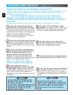
Page 2: ...rom obstruction and has a wood surface available for attaching the STB brackets The brackets may be attached to concrete if necessary but extra tools and special fasteners not supplied will be require...

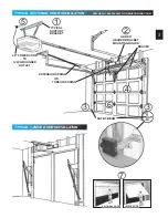
Page 3: ...54 3643 OR GENIECOMPANY COM TYPICAL SUPPORT BRACKET EXTENSION SPRING OR TORSION SPRING SAFE T BEAM BRACES ADDED HEADER BRACKET MOUNTING BOARD TYPICAL 1 PIECE DOOR INSTALLATION 48 POWER CORD TO 120V GR...

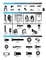
Page 4: ...m inside garage Independent light control allows convenient manual control of the automatic lighting system NOTE Your garage door operator may not come with all above items included as standard equipm...

Page 5: ...35 33 31 32 37 FASTENERS Shown Full Size See Parts List for description Lag screw 1 4 x 2 22 Screw 8 32 x 1 39 Self drilling Screw 1 4 20 x 3 4 42 Nut 1 4 20 10 Cotter pin 25 Clevis pin 24 Wire clip...

Page 6: ...800 354 3643 OR GENIECOMPANY COM 2 3 PIECE RAIL HARDWARE EXPLODED VIEW 4 10 3 9 11 25 15 16 23 28 17 27 25 26 42 24 20 12 18 47 22 9 10 41 41 10 13 39 12 10 39 14 8 9 22 18 47 7 26 42 20 24 6 9 15 11...

Page 7: ...assembly 1F Capacitor by series model 1G Opto wheel not shown 1H Carriage slide 1J Chain POWER HEAD PARTS LIST pre assembled Garage doors are large heavy objects that move with the help of springs un...

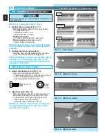
Page 8: ...refer to the instruction sheet included with the optional rail extension at this point OPEN BLUE PARTS BAG 3 Attach rail clamps to rail Fig 1 3 Use pair of clamps at both joints Fasten each pair with...

Page 9: ...l to power head magnet Make sure that the carriage magnet is in place in the top of the carriage slide CAUTION 7 Attach emergency release cord knob and tag Tie overhand knot in 1 end of cord Tighten k...

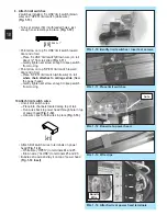
Page 10: ...Fig 1 10 Turn set screws 39 into threaded holes just enough so screw stays in place Fig 1 10 Point arrow on top CLOSE limit switch toward door end of rail Place CLOSE limit switch Brown wire on rail...

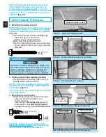
Page 11: ...ntacts a 1 1 2 inch high object on the floor at the center of the doorway This is the size of a 2 x 4 board laid flat HEADER AND DOOR MOUNTING BRACKETS 1 Finding header bracket mounting location Close...

Page 12: ...WER THAN top set of rollers Fig 2 7 For 1 piece doors door bracket must be mounted at top edge of door 4 Mounting the door bracket Proper bracing should be verified at this point Align door bracket ce...

Page 13: ...door at highest point of travel b Be level or power head slightly below level Trackless doors a Rail must clear door at highest point of travel by 1 to 1 1 2 Securely tighten power head mounting bolt...

Page 14: ...or arms sectional doors 27 28 INSTALL DOOR ARMS 1 piece doors OPEN YELLOW PARTS BAG 1 Attach the arms Straight arm to door bracket using clevis pin 24 and cotter pin 25 Fig 2 12 Curved arm to carriage...

Page 15: ...r Determine which side of garage receives most direct sunlight Fig 3 4 Red LED should always be on sunny side whenever possible Fig 3 4 For multiple doors Preventing crossed signals is critical Place...

Page 16: ...the following Insure that no part of door or its hardware is in path between lenses of source and sensor Insure that tops of lenses are between 5 6 above the floor Fig 3 9 The brackets are flexible an...

Page 17: ...2 3 Mounting Fasten wall control to wall with 2 screws 33 Fig 5 3 Remove protective backing from entrapment warning label Fig 5 4 Stick label on wall near wall control NOTE Additional wall controls ar...

Page 18: ...ushing Connect permanent wiring to power head White to white black to black ground to green Use only UL recognized wire nuts Wires inside power head must be at least 6 in length Replace motor cover an...

Page 19: ...g rail to align front edge of switch with back edge of carriage Fig 7 4 Gently tighten set screw Manually close door Place emergency release lever in engaged position Press wall control button Carriag...

Page 20: ...erference to radio communications However there is no guarantee that interference will not occur in a particular installation If this equipment does cause harmful interference to radio or television r...

Page 21: ...replacement Use coin ball point pen or similar device Gently push straight in on battery cover lock tab as shown Fig 9 1 Flip open battery cover Remove old battery Make sure new battery is facing pro...

Page 22: ...l emergency release knob toward power head to place release lever in engaged position Operate door using remote Door will re attach itself to carriage assembly 3 Contact reverse Place a 2 x 4 board la...

Page 23: ...repair properly lubricated and balanced See maintenance section Check OPEN limit switch setting See section Check OPEN FORCE adjustment See section Make sure carriage is engaged to carriage slide Plac...

Page 24: ...ser diferentes a las reglamentaciones de los Estados Unidos y del Canad antes de usar los mismos Les metteurs sont conformes la r glementation am ricaine et canadienne compter de leur date de fabrica...

Page 25: ...Juego de extensi n deslizante Una extensi n de 18 pulgadas para aumentar la carrera de un abridor deslizable de cadena para acomodar una puerta de 8 pies 2 43 m N cessaire de rallonge du Chain Glide...

Page 26: ...lit Perfect Stop GPS 5BL Stop Perfecto 34964R 04 95 Butoir Perfect Stop Chain Glide Extension Kit LCGX 8 Juego de extensi n de cadena deslizable 00001085 34 95 N cessaire de prolongement du coulisseau...

Page 27: ...___________________________________________________________________________ Dealer Address _________________________________________________________________________ City ______________________________...

Reviews: