background image

AutoRally Chassis Instructions

Version 1.4, June 2018, Georgia Institute of Technology

Summary of Contents for AutoRally

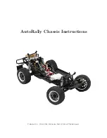
Page 1: ...AutoRally Chassis Instructions Version 1 4 June 2018 Georgia Institute of Technology...

Page 2: ......

Page 3: ...n 10 7 Steering Linkage and Side Rail Guards 18 8 Battery Box Eliminator and Steering Servo 19 9 Shocks 20 10 Axle Extenders 21 11 Wheel Rotation Sensor Magnet Mounts 24 12 Front and Rear Rotation Sen...

Page 4: ...Parts 67 27 3 Fabricated Parts 68 27 4 Upgrade Kits 68 27 5 Electronic Components 72 27 6 Connectors 78 27 7 Extra Hardware 82 27 7 1 Conversion Hardware If Using Rovan Baja Kit 82 27 7 2 Electronics...

Page 5: ...quality of solder joints crimp housing connections heat shrink coverage and wire routing are especially important for the reliability of the chassis The most common problems and often most frustrating...

Page 6: ...material 3D printed parts were made on a Dimension SST 768 1 5 Laser Cutting The GPS box lid and chassis battery fooam available in models are laser cut out of acrylic and craft foam respectively 1 6...

Page 7: ...nts only print if front brakes are not used vi 2 rear wheel rotation sensor mounts vii 2 rear wheel rotation sensor magnet mounts viii Brake servo mount 3 Fabrication Time 0 hours 30 minutes Parts 24...

Page 8: ...WN CHECKED QA MFG APPROVED aminer33 7 14 2018 DWG NO TITLE SIZE D SCALE REV 4 1 Down 90 R3 00 Up 90 R3 00 4 Laser Cutting Time 0 hours 30 minutes Parts Models for all chassis components are stl files...

Page 9: ...lid i Using the provided GPS Box Lid pdf file cut out the electronics box lid ii Roughly cut the copper sheet to the shape of the GPS box lid Apply the adhesive side of the copper sheet to the top sur...

Page 10: ...ut out 2 copies of the battery foam ii Hot glue the 2 battery foam cutouts together 5 Capacitor Precharge Circuit Time 4 hours 0 minutes Parts Castle Creations Mamba XL X ESC 1 chassis battery 6500 or...

Page 11: ...der 6 5 mm male bullets to ESC leads The leads may already be tinned by the manufacturer and might be too large for the bullet connectors Before attempting to solder into the socket you may want to sh...

Page 12: ...ation on one side of the red battery lead close to the bullet connectors and on one side of the red ESC power wire It may help to tin the exposed wire to help with the upcoming soldering h Solder the...

Page 13: ...he process in the previous step to create two red loops with 6 5 mm male connectors and two black loops with 6 5 mm male connectors Heat shrink the solder connection to ensure that no part of the conn...

Page 14: ...le in the manuals folder The item numbers in this section cor respond to those in the instructions parts list A link to videos is provided in Useful Links or they can be found in the Baja Electric Con...

Page 15: ...of side guard rails For each guard rail remove the 2 screws on the top front side 2 at the bottom rear side and 1 body clip each rear side Use provided tools with the conversion kit b Disassemble the...

Page 16: ...r brake and clutch both engine mount braces the air filter sleeve set and all engine screws on the base plate on the bottom of the chassis as shown in video 2 d Disconnect the throttle linkage and rem...

Page 17: ...tank as shown in video 2 Reserve the plastic supports that connect the tank to the aluminum chassis for the Electronics Box installation f Disconnect the steering servo and remove the battery box as s...

Page 18: ...motor with the wires facing up The video will say to install the wires with the motor wires facing to the side but disregard that instruction Additionally disregard how the wires are routed in the vid...

Page 19: ...or the motor mount plate item 3 and box frame plate item 12 at the same time l In video 4 the roll cage is installed Prior to installing the roll cage mount the passenger frame plate item 9 to the mot...

Page 20: ...plate item 11 to the box frame plate item 12 and the roll cage using three M5 15mm flat head screws n Follow electric conversion video 5 to set up the mesh Do not apply green Loctite to the motor sha...

Page 21: ...ESC with heavy duty tape and cut slots into the tape for each center slot on the ESC as shown below Mount the ESC to the diff plate using two M3 10mm screws q Install the battery foam If you are using...

Page 22: ...and Side Rail Guards Time 1 hours 0 minutes Parts Turtle Racing Billet Servo Saver Integy Side Rail Guards if available Low temperature threadlock Instructions a Complete through step 13 of the Steer...

Page 23: ...to battery box eliminator with 4 included screws ensuring correct orienta tion i To secure the steering servo into the battery box eliminator remove the 4 screws on the base of the servo and take off...

Page 24: ...om the spare parts provided with the Baja This is crucial as any different sized lock nut would obstruct the motion of the servo link arm 180 degrees c Install the battery box eliminator onto the chas...

Page 25: ...Refer to Filling with Shock Oil instructions Make sure to fill all the 4 shocks with 60w oil e Refer to Shock Spring Installation to replace the original springs with new stiffer springs f Reverse the...

Page 26: ...he top and bottom screws that hold the front axles boots to the rest of the axle assembly iii Remove the stock axle extenders and replace with the Darksouls front axle extenders iv Secure the front ax...

Page 27: ...he rest of the axle assembly b Rear axle extenders i Remove the screws from inside the rear axle extenders ii Push out the pins that hold the rear axle extenders to the drive shaft iii Remove the stoc...

Page 28: ...Mounts Time 1 hours 15 minutes Parts 2 3D printed front wheel magnet mounts if front brakes are not used 2 3D printed rear wheel magnet mounts 4x12 wheel rotation sensor magnets Arduino Due or alterna...

Page 29: ...ng tape over the holes on the side opposite the large protrusion Set a magnet in each hole so that the south pole of the magnet is touching the tape and thus facing opposite the large protrusion An ea...

Page 30: ...ervo wire c Solder one sensor to the opposite end of each of the 6 lengths of servo wire Note that the ground lead of the sensor is the middle lead so ensure that the correct wire is soldered to each...

Page 31: ...hould be installed with the protrusion facing downward as shown in the photo g Hot glue one sensor assembly to each of the sensor mounts Carefully align the sensor with the magnets on the rear rotatio...

Page 32: ...ensor magnet mount brake disc in order to ensure that the sensor will reliably detect each magnet as it passes the sensor face Note that only 4 sensor assemblies are required for the chassis 2 of the...

Page 33: ...t right disc shown on right Pay close attention to the location of the magnets as they must be aligned with the sensor but not interfere with the brake caliper or the 3D printed front brake disk align...

Page 34: ...left side of the chassis opposite side as the tranmission g Attach the 3D printed servo mount and master cylindar plate onto the chassis using 3 M3 12mm screws make sure to use low temp red or blue t...

Page 35: ...gh slack to allow the wheel to steer from side to side Refer to the pictures below for the correct routing of the tubing Make sure to measure and cut the tubing to the exact desired length before putt...

Page 36: ...h tire foams front red Zero growth tire foams back blue Instructions a Refer to the Baja 5SC manual for tire foam replacement diagrams b Remove all of the bolts on both sides of the tire Remove the be...

Page 37: ...screws realign the tire rubber and then retighten Properly seated rubber inserts will make it easier to get the beadlock to sit flush against the tire The photos show good and bad examples of seated...

Page 38: ...e components forward of the cut The remaining components are shown below c Secure remaining cut ends to shock tower with large zip ties d Cut center roll bar off just above side rail guards Discard th...

Page 39: ...PDF file in the manuals folder to locate and set the specified parameters b Apply power to the receiver while the transmitter is on and verify the transmitter connects to the receiver If not follow i...

Page 40: ...nfigure the PS2 mode to ALT alternate 17 ESC Time 0 hours 20 minutes Parts Castle Serial Link software installed from Castle Serial Link Castle Link programmer Instructions a Connect ESC to Castle Lin...

Page 41: ...le Link Programmer Instructions a Connect Castle Serial Link to Castle Link according to instructions b Use Castle Link software to change the following settings i Basic Communication Mode to TTL Seri...

Page 42: ...shows the schematic for the components within and connected to the Elec tronics Box This schematic defines the connections we will be making on the ProtoShield NOTE A scalable version of the drawings...

Page 43: ...r resistors Solder one blue wire to connect pads D9 to G9 and D14 to G14 Solder the uninsulated wire to connect pads F19 to G19 d Place and solder 2 level shifters Pin 1 of the first level shifter oct...

Page 44: ...he 1 1 2 length wire to via M9 h Cut four 3 1 2 lengths of yellow wire Solder these wires to connect pads B5 to D I O 21 SCL B6 to D I O 20 SDA B7 to D I O 19 RX1 and B8 to D I O 18 TX1 i Cut seven 1...

Page 45: ...of the servo cables introduced in step 8 to pads K3 through N3 Solder the longer red wire from step 4 to via J3 Use a section of uninsulated wire to connect all of these red wires on the bottom side o...

Page 46: ...t the blue and purple wires into a two position female 0 1 header and the green wire into a single position female 0 1 header r Solder the remaining end of the Green Blue Purple servo cable Y harness...

Page 47: ...ird space of a seven position female 0 1 header ii Solder the other blue wire to D I O 14 TX3 and crimp and insert its other end to the fourth space of the same seven position header iii Crimp and ins...

Page 48: ...8 and F18 vi E17 and F17 vii F16 and F16 viii F19 and G19 w Attach the Adafruit 5V Buzzer to the protoshield The positive long lead should be placed in pad E30 The negative short lead should be placed...

Page 49: ...DUE Assembled ProtoShield from previous step Castle Creations Serial Link Pololu RC Relay Pololu Servo Multiplexer Futaba RC Receiver 1 assembled 6 female to female servo cable extension 6 of 26 awg...

Page 50: ...k Red jumper cable by crimping and inserting each end of a 6 length of red wire and a 6 length of black wire into a two position 0 1 female header g Plug one end of the female to female two wire red b...

Page 51: ...e first position of the header red wire should connect the BUS pin and the seventh position should connect to the GND pin The blue wire from Protoshield D I O pin 15 RX3 should connect to pin A TX and...

Page 52: ...6 mm screw 3 M3 30 mm screws 3 M3 13 mm nylon spacers 2 0m male weather proof USB 2 0 cable USB breakout board Zip ties and zip tie saddle Double sided sticky foam Instructions a Epoxy nuts to the el...

Page 53: ...able into the electronics box through the steering servo cable hole on the front of the box near the base of the box d Plug the steering servo cable into the appropriate pins on the servo multiplexer...

Page 54: ...signal line while the AUX has a white signal line i Route the receiver antenna wire through the small hole near the back right top corner of elec tronics box Put a piece of double sided sticky tape t...

Page 55: ...21 ELECTRONICS BOX INSTALLATION j Cut the USB cable down to a 2 length k Solder the 4 wires into the appropriate pin slots of the USB breakout board as shown in the images below 51...

Page 56: ...een the castle serial link and the receiver m Route the brake servo extension cable to the electronics box Connect the green female 0 1 header wire from the non Y Green Blue Purple cable of the proto...

Page 57: ...o of the nylon washers as shown in the images as they do not sit flat on the Arduino q Attach the Arduino Due to the electronics box using 3 M3x40 mm screws 3 M3 nylon washers 3 M3x18 mm nylon spacers...

Page 58: ...do not fall off when the body clips are secured t Each wheel rotation sensor wire assembly has 2 parts One going from the sensors to the shock tower with Futaba J female connector assembly And the oth...

Page 59: ...e it begins signal check b Turn on the transmitter and power the ESC after sucessful calibration c Verify that steering is connected correctly by turning the steering control on the transmitter d Veri...

Page 60: ...urs 0 minutes Parts GPS box GPS box lid GPS box tab 15 12 pin GPS cable Hemisphere P307 GPS unit GPS antenna cable 4 1 4 6 32 screws for the GPS antenna 12 20 pin ribbon cable 12 pin male solder cup c...

Page 61: ...Strip approximately 1 5 insulation off one end of the 15 piece of GPS cable d Referring to the wiring diagram above solder all through wires from the ribbon cable to the GPS cable Remember to slip a...

Page 62: ...lder joind between the resistor and the black servo wire Solder the other end of the black servo wire to the ribbon cable ground wires the black lead of a 4 piece of servo cable and the ground lead of...

Page 63: ...ll exposed wire and solder k Put small pieces of heat shrink over all the free wires from the GPS cable and ribbon cable Slide a large piece of heat shrink over the GPS cable as far over the exposed w...

Page 64: ...hould be connected to the pin labeled with the small diamond mark on the GPS unit Connect the antenna to the GPS unit o Screw the GPS unit in place with 4 M3 12 screws Screw the fan in place with 2 M1...

Page 65: ...o the wiring diagram above solder the wires from the GPS cable to the appropriately numbered solder cups in the 12 pin connector Slide a small piece of heat shrink over each wire before soldering and...

Page 66: ...inutes Parts 0 5 outer diameter split loom Small zip ties Electronics box lid 4 small body clips Instructions a Heat shrink the motor shroud fan wire b Cut an 11 5 piece of split loom c Route all fan...

Page 67: ...box using the hole that exists in the chassis the engine mount brace above the side rail guards and the hole in the back plate under the ESC f Zip tie antenna to the split loom and the USB cable harne...

Page 68: ...ts in order to reduce slack to the minimum required to route these wires if needed i Zip tie front and rear wheel rotation sensor wires over the connector housings hot glued to the shock tower j Insta...

Page 69: ...under guard using body clips Then install the under guard and secure it with a body clip at the rear of the chassis See below for pictures 26 Sticker Removal Time 0 hours 30 minutes Parts Baja 5SC bod...

Page 70: ...27 APPENDIX A PARTS 27 Appendix A Parts 27 1 3D Printed Parts Electronics box Electronics box lid GPS box Front brake aligners Rear wheel rotation sensor mounts 66...

Page 71: ...27 APPENDIX A PARTS Wheel rotation sensor magnet mounts Figure 1 Front left and back right wheel rotation sensor magnet mounts Brake servo mount 27 2 Laser Cut Parts GPS Ground Plane 67...

Page 72: ...27 APPENDIX A PARTS Battery Foam 27 3 Fabricated Parts Brake master cylinder plate 27 4 Upgrade Kits Castle Creations Mamba XL X Electronic Speed Controller 68...

Page 73: ...APPENDIX A PARTS Castle Creations 2028 electric motor Castle Creations motor fan Conversion hardware kit Either Castle Creations Baja conversion hardware left or Rovan Baja conversion hardware right...

Page 74: ...27 APPENDIX A PARTS Turtle Racing Billet Servo Saver Integy side rail guards Team Fast Eddy Battery Box Eliminator Kit 70...

Page 75: ...27 APPENDIX A PARTS Savox SV 0235MG steering servo left and SV 1271TG brake servo right Shock springs front rear long rear short Shock Fluid Factory Team 60w 59 ml Darksouls Baja Axle Extender Set 71...

Page 76: ...27 APPENDIX A PARTS Mecatech front brake kit for Baja Zero growth tire foams Figure 2 Red front tire left and Blue back tire right 27 5 Electronic Components 9000 mAh 4S 14 8v Chassis Battery Pair 72...

Page 77: ...27 APPENDIX A PARTS 1900 mAh 2S LiFe 6 6V Transmitter Battery Arduino DUE Adafruit ProtoShield for DUE Baja Series Adapter 73...

Page 78: ...27 APPENDIX A PARTS Castle Serial Link Castle Link Programmer CUI 3 3V 2 4A Voltage Regulator PYB10 Q24 S3 T Futaba 4PV Transmitter with R304SB Receiver 74...

Page 79: ...27 APPENDIX A PARTS Futaba FUTM1725 Charger for Futaba 4PV Glitch Capacitor GPS antenna 75...

Page 80: ...27 APPENDIX A PARTS GPS antenna cable GPS box fan Hallogic OH090U Hall Effect sensors 76...

Page 81: ...27 APPENDIX A PARTS Hemisphere GPS P307 Pololu Level Shifter Pololu RC Relay Pololu Servo Multiplexer 77...

Page 82: ...27 APPENDIX A PARTS USB breakout board 27 6 Connectors 1 1 0 1 in header housing 1 2 0 1 in header housing 78...

Page 83: ...27 APPENDIX A PARTS 1 3 0 1 in header housing 1 4 0 1 in header housing 1 5 0 1 in header housing 1 7 0 1 in header housing 79...

Page 84: ...27 APPENDIX A PARTS 0 1 Female Crimp Pins 0 1 Male Crimp Pins Futaba J Connectors Figure 3 Male left and Female right Futaba J Connectors 80...

Page 85: ...27 APPENDIX A PARTS 4mm banana plugs 6 5mm Bullet Connectors Hirose RM 12 pin plug free hanging male pins 15mm Hirose RM bushing 81...

Page 86: ...27 APPENDIX A PARTS 27 7 Extra Hardware 27 7 1 Conversion Hardware If Using Rovan Baja Kit 2 M5 16mm button head screws 2 M3 10mm socket head screws 27 7 2 Electronics Box 3 M3 30mm screws 82...

Page 87: ...n spacers NUMBER PART Information in this drawing is provided for reference only http www mcmaster com For M3 Screw Size 18 mm 0 13 3 2 mm 0 3 0 0 4 5 mm 0 26 93657A508 Nylon Unthreaded Spacer 2017 Mc...

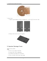
Page 88: ...27 APPENDIX A PARTS 1 M3 4mm screw 27 7 3 GPS Box 8 M3 8mm screws 4 M3 hex nuts 84...

Page 89: ...27 APPENDIX A PARTS 2 M1 4 fan screws 2 M1 4 fan nuts 2 M3 25mm screws 85...

Page 90: ...28 APPENDIX B REVISION HISTORY GPS antenna screws 4 1 4 6 32 screws 27 7 4 Front Brake 2 M3 50mm screws 28 Appendix B Revision History Revision Date Author s Description 86...

Page 91: ...box diagram spelling fixes 1 3 February 2017 BG Moved GPS power supplies into GPS box re solved inconsistencies between chassis wiring 1 4 June 2018 BG AM LP NW Updated GPS box for durability and elec...

Page 92: ......

Reviews: