background image

Hardware Manual

GV-IPCam H.264

Before attempting to connect or operate this product,
please read these instructions carefully and save this manual for future use.

Target Camera Series

ICH264TIV301

Summary of Contents for GV-EBX1100-0F

Page 1: ...Hardware Manual GV IPCam H 264 Before attempting to connect or operate this product please read these instructions carefully and save this manual for future use Target Camera Series ICH264TIV301 ...

Page 2: ...ssumed for incidental or consequential damages arising from the use of the information or products contained herein Features and specifications are subject to change without notice Note no memory card slot or local storage function for Argentina GeoVision Inc 9F No 246 Sec 1 Neihu Rd Neihu District Taipei Taiwan Tel 886 2 8797 8377 Fax 886 2 8797 8335 http www geovision com tw Trademarks used in t...

Page 3: ... 2 1 3 Overview 3 1 4 Installation 4 1 5 Connecting the Camera 6 1 6 Loading Factory Default 7 Chapter 2 Target Bullet Camera 8 2 1 Packing List 8 2 2 Features 9 2 3 Overview 10 2 4 Installation 12 2 5 Connecting the Camera 15 2 6 Loading Factory Default 17 Chapter 3 Target Mini Fixed Dome 18 3 1 Packing List 18 3 2 Features 19 i ...

Page 4: ...3 5 Connecting the Camera 24 3 6 Loading Factory Default 25 Chapter 4 Target Mini Fixed Rugged Dome 26 4 1 Packing List 27 4 2 Features 29 4 3 Overview 31 4 4 Installation 32 4 5 Connecting the Camera 39 4 6 Loading Factory Default 40 ii ...

Page 5: ...ned to provide power and network connection to the cameras over a single Ethernet cable GV POE Switch The GV POE Switch is designed to provide power along with network connection for IP devices The GV POE Switch is available in various models with different numbers and types of ports GV Mount Accessories The GV Mount Accessories provide a comprehensive lineup of accessories for installation on cei...

Page 6: ...entering the camera along the cables 2 Any PoE power audio and I O cables are waterproofed using waterproof silicon rubber or the like 3 The silica gel bag loses its effectiveness when the dry camera is opened To prevent the lens from fogging up replace the silica gel bag every time you open the camera and conceal the gel bag in camera within 2 minutes of exposing to open air ...

Page 7: ...image quality The camera supports PoE and can be installed intuitively Model No Specifications Description GV EBX1100 0F Fixed Iris f 2 8 mm F 2 0 1 2 7 M12 Mount GV EBX1100 2F Fixed Lens Fixed Iris f 3 8 mm F 1 8 1 2 7 M12 Mount 1 3 MP H 264 Low Lux D N 1 1 Packing List Target Box Camera Supporting Rack Screw x 3 Screw Anchor x 3 GV IPCAM H 264 Software DVD GV IPCAM H 264 Quick Start Guide GV NVR...

Page 8: ... microphone Wide Dynamic Range WDR Defog Motion detection Tampering alarm Text overlay Privacy mask IP address filtering DC 12V PoE IEEE 802 3af Megapixel lens NAS Recording Recording assigned by GV Edge Recording Manager Windows Mac Support for iPhone iPad Android and 3GPP 31 languages on Web interface ONVIF Profile S conformant Note For optimal performance and compatibility it is highly recommen...

Page 9: ...ls see 1 6 Loading Factory Default 2 LAN PoE Connects to a 10 100 Ethernet or PoE 3 Microphone Records sounds 4 DC 12V Terminal Block Connects to power LED Indicator Description Status LED The status LED turns on green when the system is ready for use Power LED The power LED turns on green when power is supplied to the camera 3 ...

Page 10: ...Target Box Camera 1 To install the device on the wall ceiling put the supporting rack on the desired location and make marks for screw anchors Figure 1 2 2 Drill the marks and insert the screw anchors 3 Secure the supporting rack onto the wall ceiling using the supplied screws 4 Secure the camera onto the supporting rack and fasten the indicated screw Figure 1 3 4 ...

Page 11: ... and power cables to the camera See 1 5 Connecting the Camera 6 Access the live view See 2 1 Accessing the Live View GV IPCam H 264 Firmware Manual 7 Adjust the angle of the camera based on live view and fasten the indicated screw Figure 1 4 5 ...

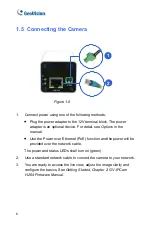
Page 12: ...il see Options in the manual Use the Power over Ethernet PoE function and the power will be provided over the network cable The power and status LEDs shall turn on green 2 Use a standard network cable to connect the camera to your network 3 You are ready to access the live view adjust the image clarity and configure the basics See Getting Started Chapter 2 GV IPCam H 264 Firmware Manual 6 ...

Page 13: ...utton on the back panel of the camera Default button Figure 1 6 3 Release the default button when the status LED blinks This shall take about 8 seconds Status LED Figure 1 7 4 When the status LED fades the process of loading default settings is completed and the camera reboots automatically When the status LED turns on green the camera is ready for use ...

Page 14: ... and excellent image quality Model No Specifications Description GV EBL1100 1F GV EBL2100 1F Fixed Iris f 6 mm F 1 8 1 2 7 M12 Mount GV EBL1100 2F GV EBL2100 2F Fixed Lens Fixed Iris f 3 8 mm F 1 8 1 2 7 M12 Mount 1 3 MP 2 MP H 264 Low Lux D N 2 1 Packing List Target Bullet Camera Sun Shield Cover Silica Gel Tape x 2 Supporting Rack Screw x 4 Screw Anchor x 3 GV IPCAM H 264 Software DVD GV IPCAM H...

Page 15: ...IR cut filter Wide Dynamic Range WDR Defog Vandal resistance IK10 for metal casing Ingress protection IP67 Motion detection Tampering alarm Text overlay Privacy mask IP address filtering DC 12V PoE IEEE 802 3af Megapixel lens NAS Recording Recording assigned by GV Edge Recording Manager Windows Mac Support for iPhone iPad Android and 3GPP 31 languages on Web interface ONVIF Profile S conformant No...

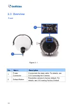
Page 16: ... 1 Figure 2 1 No Name Description 1 Power Connector Connects to the data cable For details see 2 5 Connecting the Camera 2 Default Button Resets the camera to factory default For details see 2 6 Loading Factory Default 10 ...

Page 17: ... camera cover is opened If you open the camera to access the load default button replace the silica gel tape by taping the new silica gel tape to the inside of the camera cover Make sure you conceal the silica gel tape in the camera within two minutes of exposing to the open air 11 ...

Page 18: ...Silica Gel Tape prior to installation and use waterproof tape to seal the RJ45 connector 1 Slide the sun shield cover onto the top of the camera Figure 2 2 Note The GeoVision logo on the sun shield cover should be closer to the front of the camera 2 Line up the screw hole on the camera with the opening on the sun shield cover Figure 2 3 12 ...

Page 19: ... Ceiling Mount Secure the supporting rack to the opening on the sun shield cover Figure 2 4 4 Wall Mount A Insert and tighten the supplied screw on the sun shield cover B Secure the supporting rack to the bottom Figure 2 5 13 ...

Page 20: ... a plain surface Figure 2 6 6 Remove the protection sticker from the camera s cover 7 Connect the wires and cable connector to the camera See 2 5 Connecting the Camera 8 Access the live view For details see 3 1 Accessing the Live View GV IPCam H 264 Firmware Manual 9 Adjust angles of the camera body based on the live view 14 ...

Page 21: ...onnecting the Camera Wire Definition The data cable provides connections for power ground and network access The wires are defined below Figure 2 7 No Wire Color Definition 1 Red DC 12V 2 Black Ground 3 Black thick PoE Ethernet 15 ...

Page 22: ...ed at the same time Plug the power adapter to the 12V terminal block as shown below The power adapter is an optional device For detail see Options in the manual 1 Insert the black wire of the data cable to the left pin and the red wire to the right pin Figure 2 8 2 Connect the DC 12V power adapter to the terminal block DC 12V Power Adaptor Terminal Block Figure 2 9 16 ...

Page 23: ...Loosen the camera s cover 3 Press and hold the default button for about 8 seconds Default button Figure 2 10 4 Release the default button When the process of loading default settings is completed the camera reboots automatically 5 Replace the Silica Gel Tape inside the camera cover and fasten the camera s cover immediately ...

Page 24: ...tures and excellent image quality Model No Specifications Description GV EFD1100 0F GV EFD2100 0F Fixed Iris f 2 8 mm F 2 0 1 2 7 M12 Mount GV EFD1100 2F GV EFD2100 2F Fixed Lens Fixed Iris f 3 8 mm F 1 8 1 2 7 M12 Mount 1 3 MP 2 MP H 264 Low Lux D N 3 1 Packing List Target Mini Fixed Dome Screw x 2 Screw Anchor x 2 Focus Adjustment Clip or Ring GV IPCAM H 264 Software DVD GV IPCAM H 264 Quick Sta...

Page 25: ...emovable IR cut filter 2 axis mechanism pan tilt Built in microphone Wide Dynamic Range WDR Defog Motion detection Tampering alarm Text overlay Privacy mask IP address filtering DV 12V PoE IEEE 802 3af Megapixel lens NAS Recording Recording assigned by GV Edge Recording Manager Windows Mac Support for iPhone iPad Android and 3GPP 31 languages on Web interface ONVIF Profile S conformant Note For op...

Page 26: ...Microphone Receives sound 5 Default Button Resets the camera to factory default For details see 3 6 Loading Factory Default 6 DC 12V Port Connects to power 7 LAN PoE Connects to a 10 100 Ethernet or PoE a Status Turns on green when the system is ready b Power Turns on green when power is on c Link Turns on green when the network is connected d ACT Turns on orange when data are being transmitted 20...

Page 27: ...a make sure the installing site is shielded from rain and moisture 1 Open the housing cover by turning Figure 3 2 2 Place the camera where you want to install it and make 2 marks on the ceiling or the wall for screw anchors If you want to run the cables inside the ceiling or the wall make a round mark with a diameter of 2 5 cm Figure 3 3 21 ...

Page 28: ...nd power For details see 3 5 Connecting the Camera Figure 3 4 5 Secure the Target Mini Fixed Dome to the ceiling or the wall with the supplied screws 6 Access the live view For details see 2 1 Accessing the Live View GV IPCam H 264 Firmware Manual 7 Adjust image clarity using the GV IP Device Utility program For details see 2 2 Adjusting Image Clarity GV IPCam H 264 Firmware Manual 22 ...

Page 29: ...xed Dome 3 8 Loosen the tile screw and pan screw adjust the angles based on the live view as needed and tighten the screws again Pan Screw Tilt Screw Figure 3 5 9 Place the housing cover back and turn to secure it 23 ...

Page 30: ...l see Options in the manual Use the Power over Ethernet PoE function and the power will be provided over the network cable The power and status LEDs shall turn on green 2 Use a standard network cable to connect the camera to your network 3 You are ready to access the live view adjust the image clarity and configure the basics See Getting Started Chapter 2 GV IPCam H 264 Firmware Manual 24 ...

Page 31: ...or PoE connected to the camera 2 Press and hold the default button for about 8 seconds Figure 3 7 3 Release the default button when the status LED blinks Status LED Figure 3 8 4 When the status LED fades the process of loading default settings is completed and the camera reboots automatically ...

Page 32: ...d night surveillance Adhering to IK10 and IP67 standards it offers an entry level outdoor surveillance solution with all the essential features and excellent image quality Model No Specifications Description GV EDR1100 0F GV EDR2100 0F Fixed Iris f 2 8 mm F 2 0 1 2 7 M12 Mount GV EDR1100 2F GV EDR2100 2F Fixed Lens Fixed Iris f 3 8 mm F 1 8 1 2 7 M12 Mount 1 3 MP 2 MP H 264 Low Lux D N 26 ...

Page 33: ...verter RJ 45 Connector Waterproof Rubber Set for RJ45 Waterproof Rubber Set for RJ45 and DC12V Torx Wrench Silica Gel Bag x 2 Adhesive Tape x 2 Concave Hexagon Wrench Ruler Screw for Conduit Converter x 2 GV IPCAM H 264 Quick Start Guide GV IPCAM H 264 Software DVD GV NVR Quick Start Guide GV NVR Software DVD Note Power adapter can be purchased upon request 27 ...

Page 34: ...a PG21 conduit connector and a self prepared conduit pipe of 1 2 3 4 or 1 to the camera Do not use a 1 2 pipe if you use the power adapter for power supply because the adapter cannot be threaded through A plastic PG21 conduit connector for 1 2 pipe can be purchased upon request Conduit converter Plastic PG21 conduit connector Conduit pipe 28 ...

Page 35: ...at 1920 x 1080 Intelligent IR Day and night function with removable IR cut filter 2 axis mechanism pan tilt Wide Dynamic Range WDR Defog Ingress protection IP67 Vandal resistance IK10 for metal casing Motion detection Tampering alarm Text overlay Privacy mask IP address filtering DV 12V PoE IEEE 802 3af Megapixel lens NAS Recording Recording assigned by GV Edge Recording Manager Windows Mac Suppor...

Page 36: ...Note For optimal performance and compatibility it is highly recommended to use a GV NAS System 30 ...

Page 37: ... screw to adjust pan angle 4 Default Button Resets the camera to factory default For details see 4 6 Loading Factory Default 5 DC 12V Port Connects to power 6 LAN PoE Connects to a 10 100 Ethernet or PoE a Status Turns on green when the system is ready b Power Turns on green when power is on c Link Turns on green when the network is connected d ACT Turns on orange when data are being transmitted 3...

Page 38: ...oof the cable 1 Paste the installation sticker where you want to install and drill two holes that are at a diagonal To run the cables inside the wall or ceiling drill a larger opening as shown below Figure 4 2 2 Insert the supplied screw anchors into the two drilled holes 3 Open the camera s housing cover using the supplied torx wrench Figure 4 3 32 ...

Page 39: ...ted below A back plate can be separated from the bottom Figure 4 4 5 Use the 2 supplied screws to secure the back plate onto the ceiling or the wall where the screw anchors were inserted Figure 4 5 6 Prepare an Ethernet cable with the RJ 45 connector on one end only 33 ...

Page 40: ...4 6 8 Install the supplied waterproof rubber set onto the cable s The rubber set has two parts Item 1 comes in two types 2 1 For network cable For network cable PoE For power cable Figure 4 7 A Slide the waterproof rubber set and the waterproof cap you previously removed through the cable s as shown below 2 1 Figure 4 8 34 ...

Page 41: ...g a power adapter insert the striped wire to the left pin and the other wire to the right pin Figure 4 9 D Fit item 1 to item 2 and insert them in the cable opening Use the supplied ruler to make sure the length of the cable s from the bottom of the opening to the end of the cable is under 10 cm Figure 4 10 35 ...

Page 42: ...gure 4 11 9 Thread the cable s under the black cable holder You can loosen the screw on the cable holder if needed Figure 4 12 10 Connect the camera to network and power For details see 4 5 Connecting the Camera 11 Secure the camera to the back plate by tightening the three screws as shown in Step 4 36 ...

Page 43: ...the GV IP Device Utility program For details see 2 2 Adjusting Image Clarity GV IPCam H 264 Firmware Manual 14 Loosen the tile screw and pan screw adjust the angles based on the live view as needed and tighten the screws again Figure 4 13 15 Attach the silica gel bag to the place indicated below and secure the housing cover using the torx wrench Figure 4 14 37 ...

Page 44: ...To prevent the lens from fogging up replace the silica gel bag every time you open the camera and conceal the silica gel bag within 2 minutes of exposing to open air 2 Make sure the housing cover is properly secured to prevent water from entering and damaging the inner housing 38 ...

Page 45: ... device For detail see Options in the manual Use the Power over Ethernet PoE function and the power will be provided over the network cable The power and status LEDs shall turn on green 2 Use a standard network cable to connect the camera to your network 3 You are ready to access the live view adjust the image clarity and configure the basics See Getting Started Chapter 2 GV IPCam H 264 Firmware M...

Page 46: ...onnected to the camera 2 Press and hold the default button for about 8 seconds Figure 4 16 3 Release the default button when the status LED blinks Figure 4 17 4 When the status LED fades the process of loading default settings is completed and the camera reboots automatically ...

Reviews: