
Contents:
Installation Instructions:
page 2
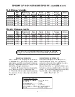
Pump Specifications:
pages 3-4
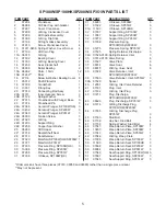
Parts List/Torque Specs.:
page 5
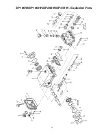
Exploded View / Kits:
page 6
Repair Instructions:
pages 7-10
Recommended Spare Parts List: page 10
Pump Mounting Selection Guide:
page
10
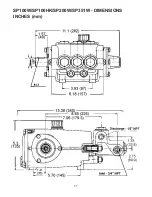
Dimensions:
page 11
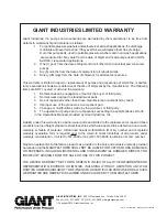
Warranty Information:
back page
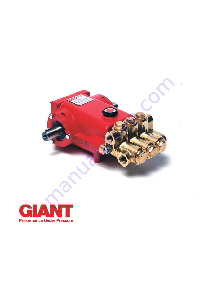
Models
SP100W/SP100HK
SP200W/SP351W
Triplex Ceramic
Plunger Pump
Operating Instructions/
Repair and Service
Manual
Updated 03/18


