background image

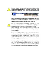
When you installing AGP card, please make sure the following notice
is fully understood and practiced.  If your AGP card has "AGP 4X/8X
(1.5V) notch"(show below), please make sure your AGP card is AGP
4X/8X (1.5V).

Caution: AGP 2X card is not supported by Intel

®

 845(GE/PE) / 845(E/G) /

850(E) / E7205 / 865(G/PE/P/GV) / 875P. You might experience system
unable to boot up normally. Please insert an AGP 4X/8X card.

Example 1: Diamond Vipper V770 golden finger is compatible with 2X/4X
mode AGP slot. It can be switched between AGP 2X(3.3V) or 4X(1.5V) mode
by adjusting the jumper. The factory default for this card is 2X(3.3V).
The GA-8I865GVMK (or any AGP 4X/8X only) motherboards might not
function properly, if you install this card without switching the jumper to
4X(1.5V) mode in it.

Example 2: Some ATi Rage 128 Pro graphics cards made by "Power Color",
the graphics card manufacturer & some SiS 305 cards, their golden finger is
compatible with 2X(3.3V)/4X(1.5V) mode AGP slot, but they support 2X(3.3V)
only. The GA-8I865GVMK (or any AGP 4X/8X only) motherboards might not
function properly, If you install this card in it.

Note : Although Gigabyte's AG32S(G) graphics card is based on ATi Rage
128 Pro chip, the design of AG32S(G) is compliance with AGP 4X(1.5V)
specification. Therefore, AG32S(G) will work fine with Intel

®

 845(GE/PE) /

845(E/G) / 850(E) / E7205 / 865(G/PE/P/GV) / 875P


based motherboards.

AGP 4 X/8 X  notc h

Summary of Contents for GA-8I865GVMK

Page 1: ...s card is 2X 3 3V The GA 8I865GVMK or any AGP 4X 8X only motherboards might not function properly if you install this card without switching the jumper to 4X 1 5V mode in it Example 2 Some ATi Rage 128 Pro graphics cards made by Power Color the graphics card manufacturer some SiS305 cards their golden finger is compatible with 2X 3 3V 4X 1 5V modeAGPslot but they support 2X 3 3V only The GA 8I865G...

Page 2: ...itment to update the information contained herein Third party brands and names are the property of their respective owners Please do not removeany labels on motherboard thismay void the warranty of this motherboard Due to rapid change in technology some of the specifications might be out of date before publication of this booklet ...

Page 3: ...mmercial and light industry o EN 55015 Limits and methods of measurement of radio disturbance characteristics of fluorescent lamps and luminaries Generic emission standard Part 2 Industrial environment o EN 55081 2 Immunity from radio interference of broadcast receivers and associated equipment Generic emission standard Part 2 Industrial environment o EN 55082 2 T EN 55022 Limits and methods of me...

Page 4: ... specifications This device complies with part 15 of the FCC Rules Operation is subject to the following two conditions 1 This device may not cause harmful and 2 this devicemust accept anyinference received including that may cause undesired operation Representative Person s Name Signature Eric Lu Supplementary Information ModelNumber GA 8I865GVMK 17358 Railroad Street City of Industry CA 91748 G ...

Page 5: ...USER S MANUAL GA 8I865GVMK P4 Titan Series Motherboard Pentium 4ProcessorMotherboard Rev 1003 12ME 8I865GV 1003 ...

Page 6: ...PU Installation 12 Step 1 2 CPU Cooling Fan Installation 13 Step 2 Install Memory Modules 14 Step 3 Install expansion cards 16 Step 4 Connect ribbon cables cabinet wires and power supply 17 Step 4 1 I O Back Panel Introduction 17 Step 4 2 Connectors Introduction 19 Chapter 3 BIOS Setup 33 The Main Menu For example BIOS Ver E5 34 Standard CMOS Features 36 Advanced BIOS Features 39 Integrated Periph...

Page 7: ...User Password 55 Save Exit Setup 56 Exit Without Saving 57 Chapter 4 Technical Reference 59 BIOS Introduction 59 EasyTune 4 Introduction 60 Flash BIOS Method Introduction 61 Method 1 Q Flash 61 Method 2 BIOS Utility 74 2 4 6 Channel Audio Function Introduction 76 Jack Sensing Introduction 82 Xpress Recovery Introduction 84 Chapter 5 Appendix 89 ...

Page 8: ... the system 5 Ensure thattheATXpowersupplyis switchedoffbefore youplug in orremove theATXpower connectoronthemotherboard Ifthe motherboard hasmounting holes buttheydon tline upwith the holes on the baseand there are no slots to attach the spacers do notbecome alarmed you can still attach the spacers to the mounting holes Justcutthe bottom portion ofthe spacers the spacermaybe a little hard to cuto...

Page 9: ...odes Can connectup to 4 IDE devices SerialATA 2 SerialATAconnectors in 150MB s operation mode Controlled by ICH5 On BoardPeripherals 1 Floppy portsupports 2 FDD with 360K 720K 1 2M 1 44M and 2 88M bytes 1 Parallel portsupports Normal EPP ECPmode 1 Serial port COMA 1 VGA port COMBon board 8 USB 2 0 1 1 ports 4 x Rear 4 x Frontby cable 1 IR CIRconnector 1FrontAudioconnector Chapter 1 Introduction to...

Page 10: ...ke up from S3 Supports BIOS SupportsEasyTune 4 Please set the CPU host frequency in accordance with your processor s specifications We don trecommend you to set the system busfrequency over the CPU s specification because these specific busfrequencies are not the standard specifications for CPU chipset and most ofthe peripherals Whether your system can run under these specific bus frequencies prop...

Page 11: ...12V CD_IN F_AU DIO F_PANEL BAT SYS_FAN Intel IC H5 Intel 865GV SOC KET 478 CPU_FAN ATX FDD IDE2 PCI1 PCI2 PCI3 DDR1 CODEC ITE8712 BIOS F_U SB2 CLR_CMOS VGA IDE1 COMB Intel 82562EZ F_U SB1 IR_CIR RAM_LED PWR_LED USB LAN R_USB AUDIO1 DDR2 DDR3 DDR4 GAME INFO_LINK SUR_CEN SATA1 SATA0 LPT ...

Page 12: ...5GV Intel ICH5 CPUCLK 100 133 200MHz System Bus 800 533 400MHz MCHCLK 100 133 200MHz 66 MHz 33 MHz 14 318 MHz 48 MHz LPCBUS 3 PCI PCICLK 33MHz RJ45 AC97 Link 8 USB Ports ATA33 66 100 IDE Channels Intel 82562EZ IT8712F 24 MHz 33 MHz Game Port Floppy LPT Port PS 2 KB Mouse 2 COM Ports MIC LINE IN LINE OUT Pentium 4 Socket 478 CPU AC97 CODEC 266 333 400MHz 2 Serial ATA DDR RAM BIOS ...

Page 13: ...Introduction English 9 ...

Page 14: ... 10 GA 8I865GVMKMotherboard English ...

Page 15: ...the Central ProcessingUnit CPU Step2 Install memorymodules Step3 Install expansion cards Step 4 Connect ribboncables cabinet wires andpower supply Congratulations Youhaveaccomplishedthe hardwareinstallation Turnon thepower supply orconnect thepowercable tothepower outlet Continue withthe BIOS softwareinstallation Step 2 Step 4 Step 4 Step 4 Step 1 Step 3 ...

Page 16: ... degreedirectly Pin1indicator 3 CPU Top View Pin1indicator 4 Locate Pin 1 in the socketand lookfora golden cutedgeonthe CPU upper corner Then insert the CPU into the socket Socket Actuation Lever Before installing the processor adhere to the following warning 1 Please make sure the CPU type is supported by the motherboard 2 If you do not match the CPU socket Pin 1 and CPU cut edge well it will cau...

Page 17: ...due to the hardening of the thermal paste During this condition if you try to remove the cool ing fan you might pull the processor out of the CPU socket alone with the cooling fan and might damage the processor To avoid this from happening we suggest you to either use thermal tape instead of thermal paste or remove the cooling fan with extreme caution 3 Make sure the CPU fan power cable is plugged...

Page 18: ...al inline memorymodule DIMM sockets The BIOS will automatically detects memory type and size To install the memory module justpush itvertically into the DIMM socket The DIMM module can only fitin one direction due to the notch Memory size can vary betweensockets DDR Notch 1 The DIMM socket has a notch so the DIMM memory module can only fit in one direction 2 Insert the DIMM memory module verticall...

Page 19: ...hen three DDR memory modules are installed part of them will not be detected 4 Four DDR memory modules are installed If you install four memory modules at the same time the Dual Channel Technology will operate only when those modules have the same memory size and type Dual Channel DDR GA 8I865GVMK supports Dual Channel Technology When Dual Channel Technology is activated the bandwidth of memory bu...

Page 20: ...laceyourcomputer schassis cover 7 Power on the computer ifnecessary setup BIOS utilityofexpansion cardfrom BIOS 8 Installrelated driverfrom theoperating system 1memory module 2memory modules DIMM 1 DIMM 2 DIMM 3 DIMM 4 DS SS X X X X X DS SS X DS SS DS SS X X l Figure 2 Don t operate Dual Channel Technology DS Double Side SS Single Side 2memory modules 4memory modules DIMM1 DIMM2 DIMM3 DIMM4 DS SS ...

Page 21: ...S 2Keyboard Connector 6pin Female v x USB LAN Connector Before you connect your device s into USB connector s please make sure yourdevice s such as USB keyboard mouse scanner zip speaker etc Have a standard USB interface Alsomakesure yourOSsupportsUSBcontroller IfyourOSdoesnotsupportUSBcontroller please contactOS vendor for possible patch or driver upgrade Formoreinformationpleasecontactyour OSor ...

Page 22: ...y connectspeakerto LineOutjack microphoneto MICIn jack Device like CD ROM walkman etc can beconnectedto Line In jack Pleasenote Youare ableto use2 4 6 channelaudiofeature by S W selection If you wantto enable 6 channel function you have2 chooseforhardwareconnection Method1 Connect FrontSpeaker to Line Out Connect RearSpeaker to Line In Connect Centerand Subwoofer to MICOut Method2 You can refer to...

Page 23: ...roduction 5 8 9 1 3 6 17 11 19 18 1 ATX_12V 2 ATX 3 CPU_FAN 4 SYS_FAN 5 FDD 6 IDE1 IDE2 7 SATA0 SATA1 8 BAT 9 F_PANEL 10 PWR_LED 11 RAM_LED 12 F_AUDIO 13 CD_IN 14 SUR_CEN 15 F_USB1 F_USB2 16 COMB 17 IR_CIR 18 GAME 19 INFO_LINK 20 CLR_CMOS 15 4 2 20 7 10 12 13 16 14 ...

Page 24: ...TXPower AC power cord should only be connected to your power supply unit after ATX power cable and other related devices are firmly connected to the mainboard PinNo Definition 1 3 3V 2 3 3V 3 GND 4 VCC 5 GND 6 VCC 7 GND 8 PowerGood 9 5VSB standby 5V 10 12V 11 3 3V 12 12V 13 GND 14 PS_ON softon off 15 GND 16 GND 17 GND 18 5V 19 VCC 20 VCC PinNo Definition 1 GND 2 GND 3 12V 4 12V 4 3 2 1 20 1 11 10 ...

Page 25: ...nt the CPU from running under abnormal condition or damaged by overheating The CPU fan connector supports Max current up to 600 mA PinNo Definition 1 GND 2 12V 3 Sense 4 SYS_FAN System Fan Connector This connector allows you to link with the cooling fan on the system case to lower the system temperature PinNo Definition 1 GND 2 12V 3 Sense 1 1 ...

Page 26: ...M 720K 1 44M and 2 88M bytes floppy disk types The red stripe of the ribbon cable must be the same side with the Pin1 6 IDE1 IDE2 IDE1 IDE2 Connector Important Notice Please connect first hard disk to IDE1 and connect CD ROM to IDE2 The red stripe of the ribbon cable must be the same side with the Pin1 1 33 2 34 39 40 IDE1 1 2 IDE2 ...

Page 27: ...s incorrectly replaced Replace only with the same or equivalent type recommended by the manufacturer Dispose of used batteries according to the manufacturer s instructions If you want to erase CMOS 1 Turn OFF the computer and unplug the power cord 2 Remove the battery wait for 30 second 3 Re install the battery 4 Plug the power cord and turn ON the computer PinNo Definition 1 GND 2 TXP 3 TXN 4 GND...

Page 28: ...tive LED Pin 1 LED anode Pin 2 LEDcathode SPEAK SpeakerConnector Pin 1 VCC Pin 2 Pin 3 NC Pin 4 Data RES ResetSwitch Open NormalOperation Close ResetHardware System PW Power Switch Open NormalOperation Close Power On Off MSG Message LED Power Sleep LED Pin 1 LED anode Pin 2 LEDcathode NC NC 1 2 1 9 2 0 HD HD RES RES NC IDE Hard Disk Active LED Reset Switch SPEAK MSG MSG PW PW Message LED Power Sle...

Page 29: ...It will blink when the system enters suspend mode If you use dual color LED power LED will turn to another color PinNo Definition 1 MPD 2 MPD 3 MPD 1 11 RAM_LED Do not remove memory modules while RAM_LED is on It might cause short or other unexpected damages due to the stand by voltage Remove memory modules only when AC power cord is disconnected ...

Page 30: ...ader your chassis must have front audio connector Also please make sure the pin assigment on the cable is the same as the pin assigment on the MB header To find out if the chassis you are buying support front audio connector please contact your dealer Please note you can have the alternative of using front audio connector or of using rear audio connector to play sound 1 10 9 2 13 CD_IN CD In Conne...

Page 31: ... 4 NoPin 5 CENTER_OUT 6 BASS_OUT 1 6 5 2 15 F_USB1 F_USB2 Front USB Connector Be careful with the polarity of the front USB connector Check the pin assignment while you connect the front USB cable Please contact your nearest dealer for optional front USB cable PinNo Definition 1 Power 2 Power 3 USB Dx 4 USBDy 5 USB Dx 6 USBDy 7 GND 8 GND 9 NoPin 10 NC 1 9 F_USB1 2 10 F_USB2 1 9 2 10 ...

Page 32: ...17 IR_CIR Make sure the pin 1 on the IR device is aling with pin one the connector To enable the IR CIR function on the board you are required to purchase an option IR CIR module For detail information please contact your autherized Giga Byte distributor To use IR function only please connect IR module to Pin1 to Pin5 Be careful with the polarity of the IR CIR connector Check the pin assignment ca...

Page 33: ...VCC 13 GPSB1 14 MSO_R 15 GPSB2 16 NoPin 18 GAME Game Connector This connector supports joystick MIDI keyboard and other relate audio devices 1 2 15 16 19 INFO_LINK This connector allows you to connect some external devices to provide you extra function PinNo Definition 1 SMBCLK 2 VCC 3 SMBDA TA 4 GPIO 5 GND 6 GND 7 NoPin 8 NC 9 12V 10 12V 1 10 2 9 ...

Page 34: ...20 CLR_CMOS Clear CMOS You may clear the CMOS data to its default values by this jumper To clear CMOS temporarily short 1 2 pin Default doesn t include the Shunter to prevent from improper use this jumper 1 1 Open Normal Close Clear CMOS ...

Page 35: ... 31 Hardware Installation Process English ...

Page 36: ... 32 GA 8I865GVMKMotherboard English ...

Page 37: ...only for Option Page Setup Menu F6 Load the file safe default CMOS value from BIOS default table F7 Load the Optimized Defaults F8 Q Flash function F9 System Information F10 Save all the CMOS changes only for Main Menu BIOS Setup is an overview of the BIOS SetupProgram The program that allows users to modify the basic system configuration This type of information is stored in battery backed CMOS R...

Page 38: ...nterAward BIOS CMOS SetupUtility the Main Menu Figure 1 will appearon the screen The MainMenuallows youto selectfrom eight setup functions andtwo exitchoices Usearrow keys to select among the items and press Enter to accept or enter the sub menu CMOS Setup Utility Copyright C 1984 2003 Award Software Standard CMOS Features Load Fail Safe Defaults Advanced BIOS Features Load Optimized Defaults Inte...

Page 39: ...ency ratio l LoadFail Safe Defaults Fail Safe Defaults indicates the value of the system parameters which the system would be in safe configuration l LoadOptimizedDefaults Optimized Defaults indicates the value of the system parameters which the system would be in best performance configuration l Set Supervisor password Change set or disable password It allows you to limit access to the system and...

Page 40: ...n to Dec Floppy 3 Mode Support Disabled Day Halt On All But Keyboard 1 to 31 or maximum allowed in the month Base Memory 640K Extended Memory 130048K Year Total Memory 131072K 1999 to 2098 higf Move Enter Select PU PD Value F10 Save ESC Exit F1 General Help F5 Previous Values F6 Fail Safe Defaults F7 Optimized Defaults Figure 2 Standard CMOS Features Date The date format is week month day year Wee...

Page 41: ...llowing items Enter the information directly from the keyboard and press Enter Such information should be provided in the documentation form your hard disk vendor or the system manufacturer CYLS Number of cylinders HEADS Number of heads PRECOMP Write precomp LANDZONE Landing zone SECTORS Number of sectors If a hard disk has not been installed select NONE and press Enter Drive A Drive B The categor...

Page 42: ... for all other errors Default value All But Diskette The system boot will not stop for a disk error it will stop for all other errors All But Disk Key The system boot will not stop for a keyboard or disk error it will stop for all other errors Memory The category is display only which is determined by POST PowerOn Self Test ofthe BIOS Base Memory The POST of the BIOS will determinethe amount of ba...

Page 43: ...B HDD Select your boot device priority by USB HDD LAN Select your boot device priority by LAN Disabled Select your boot device priority by Disabled Figure 3 Advanced BIOS Features System will detect automatically and show up when you install the Intel Pentium 4 processor with HT Technology CMOS Setup Utility Copyright C 1984 2003 Award Software Advanced BIOS Features uHard Disk Boot Priority Press...

Page 44: ...d at the prompt CPUHyper Threading Enabled Enables CPU Hyper Threading Feature Please note that this feature is only working for operating system with multi processors mode supported Default value Disabled Disables CPU Hyper Threading On Chip Frame Buffer Size 1MB Set On Chip Frame Buffer Size to 1MB 4MB Set On Chip Frame Buffer Size to 4MB 8MB Set On Chip Frame Buffer Size to 8MB 16MB Set On Chip...

Page 45: ... Enabled USB 2 0 Controller Enabled Enabled USB Keyboard Support Disabled Enable on chip IDE USB Mouse Support Disabled Port AC97 Audio Auto Onboard H W LAN Enabled Disabled Onboard LAN Boot ROM Disabled Disable on chip IDE Onboard Serial Port 1 3F8 IRQ4 Port Onboard Serial Port 2 2F8 IRQ3 UART Mode Select Normal x UR2 Duplex Mode Half Onboard Parallel Port 378 IRQ7 Parallel Port Mode SPP x ECP Mo...

Page 46: ...roller Default Value Manual Set SATA Mode manually SATAPort0 Configure as IDE Pri Master Remap SATA Port 0 to IDE Pri Master IDE Pri Slave Remap SATA Port 0 to IDE Pri Slave IDE Sec Master Remap SATA Port 0 to IDE Sec Master IDE Sec Slave Remap SATA Port 0 to IDE Sec Slave SATA Port0 SATA controller set to SATA port0 As this mode it support by WinXP or later OS only Default value SATA Port1 SATA c...

Page 47: ...Value Disabled Disable this function Onboard H W LAN Enabled Enable Onboard H W LAN function Default value Disabled Disable this function Onboard LAN Boot ROM This function decide whether to invoke the boot ROM of the onboard LAN chip Disabled Disable this function Default Value Enabled Enable this function OnboardSerial Port 1 Auto BIOS will automatically setup the port 1 address 3F8 IRQ4 Enable ...

Page 48: ...ART to IrDA Mode SCR Set onboard I O chip UART to SCR Mode Normal Set onboard I O chip UART to Normal Mode Default Value UR2 Duplex Mode Half IR Function Duplex Half Default Value Full IR Function Duplex Full OnboardParallel port 378 IRQ7 Enable onboard LPT port and address is 378 IRQ7 Default Value 278 IRQ5 Enable onboard LPT port and address is 278 IRQ5 Disabled Disable onboard LPT port 3BC IRQ7...

Page 49: ...lt Value 209 Set Game Port Address to 209 Disabled Disable this function Midi Port Address 300 Set Midi Port Address to 300 330 Set Midi Port Address to 330 Default Value Disabled Disable this function Midi Port IRQ 5 Set Midi Port IRQ to 5 10 Set Midi Port IRQ to 10 Default Value ...

Page 50: ...der x KB Power ON Password Enter ACPI OS AC BACK Function Soft Off higf Move Enter Select PU PD Value F10 Save ESC Exit F1 General Help F5 Previous Values F6 Fail Safe Defaults F7 Optimized Defaults Figure 5 Power Management Setup ACPISuspendType S1 POS Set ACPI suspend type to S1 Default Value S3 STR Set ACPI suspend type to S3 Power LEDin S1 state Blinking In standby mode S1 power LED will blink...

Page 51: ... 31 Time hh mm ss Alarm 0 23 0 59 0 59 Power On By Mouse Disabled Disabled this function Default value Mouse Click Double click on PS 2 mouse left button to power on system Power On By Keyboard Password Enter from 1 to 5 characters to set the Keyboard Power On Password Disabled Disabled this function Default value Keyboard 98 If your keyboard have POWER Key button you can press the key to power on...

Page 52: ...10 11 12 14 15 Set IRQ 3 4 5 7 9 10 11 12 14 15 to PCI 2 PCI3 IRQ Assignment Auto Auto assign IRQ to PCI 3 Default value 3 4 5 7 9 10 11 12 14 15 Set IRQ 3 4 5 7 9 10 11 12 14 15 to PCI 3 CMOS Setup Utility Copyright C 1984 2003 Award Software PnP PCI Configurations PCI 1 IRQ Assignment Auto Item Help PCI 2 IRQ Assignment Auto Menu Level u PCI 3 IRQ Assignment Auto higf Move Enter Select PU PD Val...

Page 53: ...status automatically CMOS Setup Utility Copyright C 1984 2003 Award Software PC Health Status Vcore OK Item Help DDR25V OK Menu Level u 3 3V OK 12V OK Current CPU Temperature 40 C Current CPU FAN Speed 6490 RPM Current SYSTEM FAN Speed 0 RPM CPU Warning Temperature Disabled CPU FAN Fail Warning Disabled SYSTEM FAN Fail Warning Disabled higf Move Enter Select PU PD Value F10 Save ESC Exit F1 Genera...

Page 54: ...0 C 176 F Monitor CPU Temp at 80 C 176 F 90 C 194 F Monitor CPU Temp at 90 C 194 F 8Disabled Disable this function Default value CPUFAN Fail Warning Disabled Fan Warning Function Disable Default value Enabled Fan Warning Function Enable SYSTEMFAN Fail Warning Disabled Fan Warning Function Disable Default value Enabled Fan Warning Function Enable ...

Page 55: ... Ratio This option will not be shown or not be available if you are using a CPU with the locked ratio 15X 21X It depends on CPU Clock Ratio This setup option will automatically assign by CPU detection For C Stepping P4 8X 10X 24X default 15X For Northwood CPU 12X 24X default 16X The option will display Locked and read only if the CPU ratio is not changeable CPUHost Clock Control Note If system han...

Page 56: ...quency Host clock X 2 0 2 66 Memory Frequency Host clock X 2 66 Auto Set Memory frequency by DRAM SPD data Default value for FSB Front Side Bus frequency 533MHz 2 0 Memory Frequency Host clock X 2 0 2 5 Memory Frequency Host clock X 2 5 Auto Set Memory frequency by DRAM SPD data Default value for FSB Front Side Bus frequency 800MHz 2 0 Memory Frequency Host clock X 2 0 1 6 Memory Frequency Host cl...

Page 57: ...Software Standard CMOS Features Load Fail Safe Defaults Advanced BIOS Features Load Optimized Defaults Integrated Peripherals Set Supervisor Password Power Management Setup Set User Password PnP PCI Configurations Save Exit Setup PC Health Status Exit Without Saving Frequency Voltage Control ESC Quit higf Select Item F8 Q Flash F10 Save Exit Setup Load Fail Safe Defaults Figure 9 Load Fail Safe De...

Page 58: ...Award Software Standard CMOS Features Load Fail Safe Defaults Advanced BIOS Features Load Optimized Defaults Integrated Peripherals Set Supervisor Password Power Management Setup Set User Password PnP PCI Configurations Save Exit Setup PC Health Status Exit Without Saving Frequency Voltage Control ESC Quit higf Select Item F8 Q Flash F10 Save Exit Setup Load Optimized Defaults Figure 10 Load Optim...

Page 59: ...S Setup program function When enabled the Supervisor password is required for entering the BIOS Setup program andhaving full configuration fields the User password is required to access only basic items If y ou select System at Passw ord C heck inAdvance BIOS Features Menu you will be prompted for thepasswordevery time the system is rebooted or any time youtry to enter Setup Menu If youselect Setu...

Page 60: ...tware Standard CMOS Features Load Fail Safe Defaults Advanced BIOS Features Load Optimized Defaults Integrated Peripherals Set Supervisor Password Power Management Setup Set User Password PnP PCI Configurations Save Exit Setup PC Health Status Exit Without Saving Frequency Voltage Control ESC Quit higf Select Item F8 Q Flash F10 Save Exit Setup Save Data to CMOS Figure 12 Save Exit Setup Save to C...

Page 61: ...d CMOS Features Load Fail Safe Defaults Advanced BIOS Features Load Optimized Defaults Integrated Peripherals Set Supervisor Password Power Management Setup Set User Password PnP PCI Configurations Save Exit Setup PC Health Status Exit Without Saving Frequency Voltage Control ESC Quit higf Select Item F8 Q Flash F10 Save Exit Setup Abandon all Data Figure 13 Exit Without Saving Quit Without Saving...

Page 62: ... 58 GA 8I865GVMK Motherboard English ...

Page 63: ...date software It could help you to download the BIOS from internetand update it Not like the other BIOS update software it s a Windows utility With the help of BIOS BIOS updating is no more than a click Besides no matter which mainboard you are using if it s a Gigabyte s product BIOS help you tomaintain the BIOS This utilitycould detect yourcorrectmainboard model and helpyou tochoose the BIOS acco...

Page 64: ...U speed automatically with the result being shown in the control panel If users prefer Overclock by them there is also another choice Click Advanced Mode to enjoy sport drive class Overclocking user interface Advanced Mode allows users to change the system bus AGP Memory working frequency in small increments to get ultimate system performance It operates in coordinationwithGigabyte motherboards Be...

Page 65: ... do it with caution We are sorry that GigabyteTechnology Co Ltd is not responsible for damages of system because of incorrect manipulation of updating BIOS to avoid any claims from end users BeforeYou Begin Before you start updating BIOS with the Q Flash utility please follow the steps below first 1 Download the latest BIOS for your motherboard from Gigabyte s website 2 Extract the BIOS file downl...

Page 66: ...g BIOS with Q Flash Utility on Dual BIOS Motherboards Some of Gigabyte motherboards are equipped with dual BIOS In the BIOS menu of the motherboards supporting Q Flash and Dual BIOS the Q Flash utility and Dual BIOS utility are combined in the same screen This section only deals with how to use Q Flash utility In the following sections we take GA 7VRXP as the example to guide you how to flash BIOS...

Page 67: ...OAD OPTIMIZED DEFAULTS EXIT WITHOUT SAVING ESC Quit hifg Select Item F5 Old Values F6 Fail Safe Values F7 Optimized Values F8 Dual BIOS Q Flash F10 Save Exit Load Fail Safe Defaults ENTER DUAL BIOS Q FLASH UTILITY Y N Y Dual BIOS Utility Boot From Main Bios Main ROM Type Size SST 49LF003A 256K Backup ROM Type Size SST 49LF003A 256K Wide Range Protection Disable Boot From Main Bios Auto Recovery En...

Page 68: ... a floppy disk having the BIOS file for your motherboard and insert it to your computer If you have already put the floppy disk into your system and have entered the Q Flash utility please follow the steps below to flash BIOS Steps 1 Press arrow buttons on your keyboard to move the light bar to Load Main BIOS from Floppy item in the Q Flash menu and press Enter button If you want to save the curre...

Page 69: ...Recovery Enable Halt On Error Disable Copy Main ROM Data to Backup Load Default Settings Save Settings to CMOS Q Flash Utility Load Main BIOS from Floppy Load Backup BIOS from Floppy Save Main BIOS to Floppy Save Backup BIOS to Floppy Enter Run hi Move ESC Reset F10 Power Off Dual BIOS Utility Boot From Main Bios Main ROM Type Size SST 49LF003A 256K Backup ROM Type Size SST 49LF003A 256K Wide Rang...

Page 70: ...oad Backup BIOS from Floppy Save Main BIOS to Floppy Save Backup BIOS to Floppy Enter Run hi Move ESC Reset F10 Power Off You can press Enter to continue updating BIOS or ESC to abort CHECKSUM 96D2 Are you sure to update BIOS Enter to continue or Esc to abort Dual BIOS Utility Boot From Main Bios Main ROM Type Size SST 49LF003A 256K Backup ROM Type Size SST 49LF003A 256K Wide Range Protection Disa...

Page 71: ...ttings Save Settings to CMOS Q Flash Utility Load Main BIOS from Floppy Load Backup BIOS from Floppy Save Main BIOS to Floppy Save Backup BIOS to Floppy Enter Run hi Move ESC Reset F10 Power Off Are you sure to RESET Enter to continue or Esc to abort Dual BIOS Utility Boot From Main Bios Main ROM Type Size SST 49LF003A 256K Backup ROM Type Size SST 49LF003A 256K Wide Range Protection Disable Boot ...

Page 72: ...VISOR PASSWORD POWERMANAGEMENTSETUP USER PASSWORD PNP PCI CONFIGURATION IDE HDD AUTO DETECTION LOAD FAIL SAFE DEFAULTS SAVE EXIT SETUP LOAD OPTIMIZED DEFAULTS EXIT WITHOUT SAVING ESC Quit hifg Select Item F5 Old Values F6 Fail Safe Values F7 Optimized Values F8 Dual BIOS Q Flash F10 Save Exit Load Fail Safe Defaults Press Enter on your keyboard After system reboots you may find the BIOS version on...

Page 73: ...defaults Load Fail Safe Defaults Y N Y 7 Select Save Exit Setup item to save the settings to CMOS and exit the BIOS menu System will reboot after you exit the BIOS menu The procedure is completed AMIBIOS SIMPLE SETUP UTILITY VERSION 2 00 C 2001 American Megatrends Inc All Rights Reserved STANDARD CMOS SETUP INTEGRATED PERIPHERALS BIOSFEATURES SETUP HARDWARE MONITOR MISC SETUP CHIPSETFEATURES SETUP...

Page 74: ... Password PnP PCI Configurations Set User Password PC Health Status Save Exit Setup Frequency Voltage Control Exit Without Saving ESC Quit higf Select Item F8 Q Flash F10 Save Exit Setup Time Date Hard Disk Type 2 Press F8 on your keyboard and then Y button to enter the Q Flash utility CMOS Setup Utility Copyright C 1984 2002 Award Software Standard CMOS Features Top Performance Advanced BIOS Feat...

Page 75: ...nedon yourkeyboard to performthese actions Using the Q Flash utility This section tells you how to update BIOS using the Q Flash utility As described in the Before you begin section above you must prepare a floppy disk having the BIOS file for your motherboard and insert it to your computer If you have already put the floppy disk into your system and have enter the Q Flash utility please follow th...

Page 76: ...1 30 Flash Type Size SST 49LF002A 256K Enter Run h i Move ESC Reset F10 Power Off Keep DMI DataEnable Update BIOS from Floppy Save BIOS to Floppy 8GE800 F4 256K Total Size 1 39M Free Size 1 14M F5 Refresh DEL Delete 1 File s found BIOS file in the floppy Q Flash Utility V1 30 Flash Type Size SST 49LF002A 256K Enter Run h i Move ESC Reset F10 Power Off Keep DMI DataEnable Update BIOS from Floppy Sa...

Page 77: ...Floppy Save BIOS to Floppy Updating BIOS Now Do not Turn Off Power On RESET System 4 Press any keys to return to the Q Flash menu when the BIOS updating procedure is completed 5 Press Esc and then Enter to exit the Q Flash utility System will restart Q Flash Utility V1 30 Flash Type Size SST 49LF002A 256K Enter Run h i Move ESC Reset F10 Power Off Keep DMI DataEnable Update BIOS from Floppy Save B...

Page 78: ...Select the exact model name on your motherboard e System will automatically download and update the BIOS Method 2 BIOS Utility 3 1 4 2 4 Please select BIOS sever site then Click OK If you don t have DOS boot disk we recommend that you used Gigabyte BIOS program to flash BIOS 3 Click P Click here 2 Click Start All Programs GIGABYTE BIOS 1 Click BIOS item Press here ...

Page 79: ...very beginning there is About this program icon shown in dialog box It can help you check out which kind of motherboard and which brand of Flash ROM are supported Note a In method I if it shows two or more motherboard s model names to be selected please make sure your motherboard s model name again Selecting wrong model name will cause the system unbooted b In method II be sure that motherboard s ...

Page 80: ...TEP 1 Connect the stereo speakers or earphone to Line Out The installation of Windows 98SE 2K ME XP is very simple Please follow next step to install the function Line Out STEP 3 Select Speaker Configuration and choose the 2 channel for stereo speakers out put STEP 2 After installation of the audio driver you ll find an icon on the taskbar s status area Click the audio icon Sound Effect from the w...

Page 81: ...on the taskbar s status area Click the audio icon Sound Effect from the windows tray at the bottom of the screen Line Out Line In STEP 3 Select Speaker Configuration and choose the 4 channel for 4 speakers out put Disable Only SURROUND KIT and press OK When the Environment settings is None the sound would be performed as stereo mode 2 chan nels output Please select the other settings for 4 channel...

Page 82: ... Center Subwoofer channels to MIC In Basic 6 Channel Analog Audio Output Mode Line Out Line In MIC In STEP 2 After installation of the audio driver you ll find an icon on the taskbar s status area Click the audio icon Sound Effect from the windows tray at the bottom of the screen STEP 3 Select Speaker Configuration and choose the 6 channel for 5 1 speakers out put Disable Only SURROUND KIT and pes...

Page 83: ...og Audio Output Mode using SURROUND KIT Optional Device SURROUND KIT provides Rear R L and Center subwoofer SURROUND KIT access analog output to rear channels and Center Subwoofer channels It is the best solution if you need 6 channel output Line In and MIC at the same time STEP 2 Connect the SURROUND KIT to SUR_CEN on the motherboard ...

Page 84: ...ROUND KIT s REAR R L and the Center Subwoofer channels to SURROUND KIT s SUB CENTER STEP 5 Select Speaker Configuration and choose the 6 channels for 5 1 speakers out put Enable Only SURROUND KIT and press OK When the Environment settings is None the sound would be performed as stereo mode 2 chan nels output Please select the other settings for 6 channels output Basic Advanced 6 Channel Analog Aud...

Page 85: ... or others output devices to Line Out jack and microphone to MIC In jack Jack Sensing includes 2 parts AUTO and MANUAL Following is an example for 2 channels Windows XP Please connect the devices to the right jacks as above A window will appear as right picture if you setup the devices properly Please note that 3D audio function will only appear when 3D audio inputs Auto detecting Jack Sensing pro...

Page 86: ...K Motherboard English Manual setting If the device picture shows different from what you set please press Manual Selection to set If you set wrong with the connectors the warning message will come out as right picture ...

Page 87: ...ing speed will affect backing up speed 2 We recommend that you install Xpress Recovery immediately after installing O S drivers and applications How to use the Xpress Recovery There are two ways to enter the Xpress Recovery utility see the below 1 Text Mode press F9 during powering on the computer 2 BMP Mode boot from CD ROM Boot from CD VerifyingDMIPoolData BootfromCD Please go to Advanced BIOS s...

Page 88: ...u ll still be directed to BMP mode by pressing F9 in the bootup screen Xpress Recovery V1 0 C CopyRight 2003 GIGABYTE TechnilogyCO Ltd 1 Execute Backup Utility 2 Execute Restore Utility 3 Remove Backup Image 4 Exit and Restart Text Mode BMPMode Xpress Recovery V1 0 C CopyRight 2003 GIGABYTE TechnilogyCO Ltd 1 Execute Backup Utility 2 Execute Restore Utility 3 Remove Backup Image 4 Exit and Restart...

Page 89: ...p it The backed up data will be saved as an hidden image 2 Execute Restore Utility This program will recover your system to factory default Press R to recover your system Press Esc to exit Restorethe backupimage tothe originalstate 3 Remove Backup Image Are you sure to remove backup image Y N Remove the backup image 4 Exit and Restart Exit and restart your computer ...

Page 90: ... 86 GA 8I865GVMK Motherboard English ...

Page 91: ...Technical Reference 87 English ...

Page 92: ... 88 GA 8I865GVMK Motherboard English ...

Page 93: ... This page shows the drivers that need to be installed for the system Click each item to install the driver manually or switch to the to install the drivers automatically The Xpress Install uses the Click and Forget technology to install the drivers automatically Just select the drivers you want then click the GO button The will finish the installation for you automatically We recommend that you i...

Page 94: ...less Ethernet connections n RealTek AC97 Codec Driver For Intel ICH ICH2 ICH4 ICH5 ICH5R AC97 audio n Intel USB 2 0 Driver It is recommended that you use the Microsoft Windows update for the most updated driver for XP 2K Item Description Driver installation finished You have to reboot system For USB2 0 driver support under Windows XP operating system please use Windows Service Pack After install W...

Page 95: ... overclocking and hardware monitoring functions n DMI Viewer Windows based utility which is used to browse the DMI SMBIOS information of the system n Face Wizard New utility for adding BIOS logo n BIOS Gigabyte windows flash BIOS utility n Acrobat e Book Useful utility from Adobe n Acrobat Reader Popular utility from Adobe for reading PDF file format documents n Norton Internet Security NIS Integr...

Page 96: ...rd English SOFTWARE INFORMATION This page list the contects of softwares and drivers in this CD title HARDWARE INFORMATION This page lists all device you have for this motherboard CONTACT US Please see the last page for details ...

Page 97: ...Utilities Installation Powerful utility that integrates the overclocking and hardware monitoring functions 1 2 4 1 Click EasyTune4 item 2 Click Next 3 6 5 3 Click Finish to restart computer 4 Right Click the icon to start EasyTune 4 ...

Page 98: ...f power 2 Disconnect the power cord from MB 3 Take out the battery gently and put it aside for about 10 minutes Or you can use a metal object to connect the positive and negative pins in the battery holder to makethem short for one minute 4 Re insert the battery to the battery holder 5 Connect power cord to MB again and turn on power 6 Press Del to enter BIOS and load Fail Safe Defaults 7 Save cha...

Page 99: ...e situations might differ from case to case gAMI BIOS Beep Codes Computer gives 1 short beep when system boots successfully Except for beep code 8 these codes are always fatal 1 beep Refresh failure 2 beeps Parity error 3 beeps Base 64K memory failure 4 beeps Timer not operational 5 beeps Processor error 6 beeps 8042 gate A20 failure 7 beeps Processor exception interrupt error 8 beeps Display memo...

Page 100: ...peed frequency ratio voltage and etc are set properly Failure has been excluded Check if the CPU cooling fan attached to CPU properly ls CPU cooling fan power connected to CPU_FAN properly Plug the CPU cooling fan power in the CPU fan connector Plug in the AC power connector Check if the memory install properly into the DIMM slot Yes No Yes Insert and push the memory module vertically into the DIM...

Page 101: ...m tw The appropriate response will be provided ASAP Is memory LED on and CPU fan running The problem could be caused by power supply CPU memory or CPU memory socket itself Check if there is display Perhaps your VGA card VGA slot or monitor is defective Turn off the system Reboot after keyboard and mouse have been plugged in Check if keyboard is working properly It is possible that your keyboard or...

Page 102: ... Phone No Contact Person E mail Add Model name Lot Number PCB revision BIOS version O S A S Hardware Mfs Model name Size Driver Utility Configuration CPU Memory Brand Video Card Audio Card HDD CD ROM DVD ROM Modem Network AMR CNR Keyboard Mouse Power supply Other Device Problem Description ...

Page 103: ...ation and Networking Riser DMA Direct Memory Access DMI Desktop Management Interface DIMM Dual Inline Memory Module DRM Dual Retention Mechanism DRAM Dynamic Random Access Memory DDR Double Data Rate ECP Extended Capabilities Port ESCD Extended System Configuration Data ECC Error Checking and Correcting EMC Electromagnetic Compatibility EPP Enhanced Parallel Port ESD Electrostatic Discharge FDD Fl...

Page 104: ...ting Diode MHz Megahertz MIDI Musical Instrument Digital Interface MTH Memory Translator Hub MPT Memory Protocol Translator NIC Network Interface Card OS Operating System OEM Original Equipment Manufacturer PAC PCI A G P Controller POST Power On Self Test PCI Peripheral Component Interconnect RIMM Rambus in line Memory Module SCI Special Circumstance Instructions SECC Single Edge Contact Cartridge...

Page 105: ... 101 English Memo ...

Page 106: ... 102 GA 8I865GVMK Motherboard English ...

Page 107: ... 103 English Memo ...

Page 108: ... 104 GA 8I865GVMK Motherboard English ...

Page 109: ...Appendix 105 English ...

Page 110: ... 106 GA 8I865GVMK Motherboard English ...

Page 111: ...de giga byte com TechSupport ServiceCenter htm Non Tech Support Sales Marketing http ggts gigabyte com tw nontech asp WEB address http www gigabyte de Contact Us Japan NIPPON GIGA BYTE CORPORATION WEB address http www gigabyte co jp Singapore GIGA BYTE SINGAPORE PTE LTD Tech Support http tw giga byte com TechSupport ServiceCenter htm Non Tech Support Sales Marketing http ggts gigabyte com tw nonte...

Page 112: ...p www giga byte com au TechSupport ServiceCenter htm Non Tech Support Sales Marketing http ggts gigabyte com tw nontech asp WEB address http www giga byte com au France GIGABYTE TECHNOLOGY FRANCES S A R L Tech Support http tw giga byte com TechSupport ServiceCenter htm Non Tech Support Sales Marketing http ggts gigabyte com tw nontech asp WEB address http www gigabyte fr Russia Moscow Representati...

Reviews: