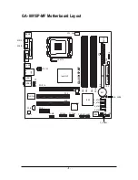
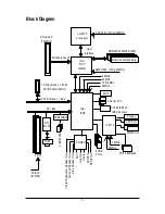
background image

GA-8I915P-MF

Intel

®

 Pentium

®

 4 LGA775 Processor Motherboard

User's Manual

Rev. 2202
12ME-8I915PMF-2202

* The WEEE marking on the product indicates this product must not be disposed of with user's other household waste

and must be handed over to a designated collection point for the recycling of waste electrical and electronic equipment!!

* The WEEE marking applies only in European Union's member states.

Summary of Contents for GA-8I915P-MF

Page 1: ...02 The WEEE marking on the product indicates this product must not be disposed of with user s other household waste and must be handed over to a designated collection point for the recycling of waste electrical and electronic equipment The WEEE marking applies only in European Union s member states ...

Page 2: ...Motherboard GA 8I915P MF Jun 11 2004 Jun 11 2004 Motherboard GA 8I915P MF ...

Page 3: ...en permission Specifications and features are subject to change without prior notice Product Manual Classification In order to assist in the use of this product Gigabyte has categorized the user manual in the following For detailed product information and specifications please carefully read the Product User Manual For detailed information related to Gigabyte s unique features please go to the Tec...

Page 4: ... 5 Install expansion cards 16 1 6 I O Back Panel Introduction 17 1 7 ConnectorsIntroduction 18 Chapter 2 BIOS Setup 29 The Main Menu For example BIOS Ver F4 30 2 1 Standard CMOS Features 32 2 2 Advanced BIOS Features 34 2 3 IntegratedPeripherals 36 2 4 Power Management Setup 39 2 5 PnP PCI Configurations 41 2 6 PC Health Status 42 2 7 MB Intelligent Tweaker M I T 43 2 8 LoadFail SafeDefaults 44 2 ...

Page 5: ...CD Information 48 3 4 HardwareInformation 49 3 5 Contact Us 49 Chapter 4 Appendix 51 4 1 Unique Software Utilities 51 4 1 1 EasyTune 5 Introduction 52 4 1 2 Xpress Recovery Introduction 53 4 1 3 Flash BIOS Method Introduction 56 4 1 4 2 4 6 8 Channel Audio Function Introduction 65 4 2 Troubleshooting 69 ...

Page 6: ...23 RTL8110S S_ATA0 ICH6 BIOS PCI1 PCI2 DDR1 DDR2 DDR3 DDR4 S_ATA3 S_ATA2 S_ATA1 FDD PWR_LED F_PANEL CLR_CMOS F1_1394 F2_1394 PCIE_16 PCIE_1 F_USB2 F_USB1 COMB CODEC COMA LPT USB LAN CD_IN AZALIA_FP Intel 915P AUDIO1 ATX IDE R_USB GA 8I915P MF IT8712 SPDIF_O SPDIF_I AUDIO2 SYS_FAN ...

Page 7: ... GMCHCLK 133 200MHz 66MHz 48MHz PCI Bsu 4 Serial ATA IT 8712 ATA33 66 100 IDE Channels LPT Port COM Ports Floppy PS 2 KB Mouse 24MHz 33MHz 8 USB Ports Intel ICH6 CODEC Line Out MIC Line In SPDIF In SPDIF Out Side Speaker Out Center Subwoofer Speaker Out Surround Speaker Out 2 PCI PCICLK 33MHz RTL 8110S RJ45 PCI ECLK 100MHz 1 PCIExpress x 1Ports PCI ECLK 100MHz PCI Express x1 Bus ...

Page 8: ... 8 ...

Page 9: ... the motherboard or any hardware please first carefully read the information in the provided manual 3 Before using the product please verify that all cables and power connectors are connected 4 To prevent damage to the motherboard please do not allow screws to come in contact with the motherboard circuit or its components 5 Please make sure there are no leftover screws or metal components placed o...

Page 10: ...mal EPP ECP mode 1 COMA port onboard COMB connection 8 USB 2 0 1 1 ports rear x 4 front x 4 via cable 3 IEEE1394 ports requires cable 1 front audio connector 1 IR connector 1 PS 2 keyboard port 1 PS 2 mouse port Onboard LAN Onboard Realtek 8110S chip 10 100 1000 Mbit 1 RJ 45 port Onboard Audio ALC880 CODEC High Definition Audio Supports 2 4 6 8 channel audio Supports Line In Line Out Front Speaker...

Page 11: ...eed detection CPU warning temperature CPU System fan failure warning CPU smart fan control BIOS Use of licensed AWARD BIOS Supports Q Flash Additional Features Supports BIOS Supports EasyTune5 only supports Hardware Monitor function Overclocking Over Clock via BIOS DDR Form Factor Micro ATX form factor 24 4 cm x 24 4cm ...

Page 12: ...ations including the CPU graphics card memory hard drive etc HT functionality requirement content Enabling the functionality of Hyper Threading Technology for your computer system requires all of the following platform components CPU An Intel Pentium 4 Processor with HT Technology Chipset An Intel Chipset that supports HT Technology BIOS A BIOS that supports HT Technology and has it enabled OS An ...

Page 13: ...ink atop the CPU and make sure the push pins aim to the pin hole on the motherboard Pressing down the push pins diagonally Fig 2 Turning the push pin along the direction of arrow is to remove the heatsink on the contrary is to install Please note the direction of arrow sign on the male push pin doesn t face inwards before installation This instruction is only for Intel boxed fan Fig 4 Please make ...

Page 14: ...e designed so that they can be inserted only in one direction The memory capacity used can differ with each slot Before installing the memory modules please comply with the following conditions 1 Please make sure that the memory used is supported by the motherboard It is recommended that memory of similar capacity specifications and brand be used 2 Before installing or removing memory modules plea...

Page 15: ...hree DDR memory modules are installed Please note that The Dual Channel Technology will not operate when three DDR memory modules are installed part of them will not be detected 4 Four DDR memory modules are installed If you install four memory modules at the same time the Dual Channel Technology will operate only when those modules have the same memory size and type We ll strongly recommend our u...

Page 16: ...he card are indeed seated in the slot 5 Replace the screw to secure the slot bracket of the expansion card 6 Replace your computer s chassis cover 7 Power on the computer if necessary setup BIOS utility of expansion card from BIOS 8 Install related driver from the operating system Installing a PCI Express x 16 expansion card Please carefully pull out the small white drawable bar at the end of the ...

Page 17: ...a processing devices USB port Before you connect your device s into USB connector s please make sure your device s such as USB keyboard mouse scanner zip speaker etc have a standard USB interface Also make sure your OS supports USB controller If your OS does not support USB controller please contact OS vendor for possible patch or driver upgrade For more information please contact your OS or devic...

Page 18: ... PWR_LED 10 AZALIA_FP 11 CD_IN 12 F_USB1 F_USB2 13 F1_1394 F2_1394 14 IR 15 COMB 16 CLR_CMOS 17 BAT 1 3 5 2 8 11 14 17 16 12 10 4 6 7 9 13 15 Center Subwoofer Speaker Out Connect the Center Subwoofer speakers to this connector Side Speaker Out Connect the side surround speakers to this connector You can use audio software to configure 2 4 6 8 channel audio functioning ...

Page 19: ... able to handle the system voltage requirements It is recommended that a power supply that can withstand high power consumption be used 300W or greater If a power supply is used that does not provide the required power the result can lead to an unstable system or a system that is unable to start If you use a 24 pin ATX power supply please remove the small cover on the power connector on the mother...

Page 20: ...wer connector supplies a 12V power voltage via a 3 pin 4 pin only for CPU_FAN power connector and possesses a foolproof connection design Most coolers are designed with color coded power connector wires A red power connector wireindicates a positive connection and requires a 12V power voltage The black connector wire is the ground wire GND Please remember to connect the power to the cooler to prev...

Page 21: ... two IDE devices please set the jumper on one IDE device as Master and the other as Slave for information on settings please refer to the instructions located on the IDE device 1 7 Pin No Definition 1 GND 2 TXP 3 TXN 4 GND 5 RXN 6 RXP 7 GND 1 2 39 40 7 S_ATA0 S_ATA1 S_ATA2 S_ATA3 Serial ATA Connector Controlled by ICH6 Serial ATA can provide 150MB s transfer rate Please refer to the BIOS setting f...

Page 22: ...ctive LED Pin 1 LED anode Pin 2 LED cathode SPEAK Speaker Connector Pin 1 VCC Pin 2 Pin 3 NC Pin 4 Data RES Reset Switch Open Normal Operation Close Reset Hardware System PW Power Switch Open NormalOperation Close Power On Off MSG Message LED Power Sleep LED Pin 1 LED anode Pin 2 LED cathode NC NC 1 2 19 20 HD HD RES RES NC SPEAK MSG MSG PW PW SPEAK Speaker Connector IDE Hard Disk Active LED Messa...

Page 23: ...you connect the audio panel cable incorrect connection between the cable and connector will make the device unable to work or even damage it For optional audio panel cable please contact your local dealer Pin No Definition 1 MIC2_L 2 GND 3 MIC2_R 4 ACZ_DET 5 Line2_R 6 FSENSE1 7 FAUOIO_JD 8 No Pin 9 LINE2_L 10 FSENSE2 Pin No Definition 1 MIC 2 GND 3 MIC Power 4 N A 5 Line Out R 6 N A 7 N A 8 No Pin...

Page 24: ...f the front USB connector Check the pin assignment carefully while you connect the front USB cable incorrect connection between the cable and connector will make the device unable to work or even damage it For optional front USB cable please contact your local dealer The USB Device Wake up From S3 is only supported by rear USB ports Pin No Definition 1 Power 2 Power 3 USBDX 4 USB Dy 5 USBDX 6 USB ...

Page 25: ...our nearest dealer for optional IR device 1 2 16 1 15 13 F1_1394 F2_1394 IEEE1394Connector Serial interface standard set by Institute of Electrical and Electronics Engineers which has features like high speed high bandwidth and hot plug Be careful with the polarity of the IEEE1394 connector Check the pin assignment carefully while you connect the IEEE1394 cable incorrect connection between the cab...

Page 26: ...CMOS temporarily short 1 2 pin Default doesn t include the Shunter to prevent from improper use this jumper 1 1 Open Normal Short Clear CMOS 15 COMB Serial Port Connector Be careful with the polarity of the COM connector Check the pin assignment carefully while you connect the COM cable incorrect connection between the cable and connector will make the device unable to work or even damage it For o...

Page 27: ...h the same or equivalent type recommended by the manufacturer Dispose of used batteries according to the manufacturer s instructions If you want to erase CMOS 1 Turn OFF the computer and unplug the power cord 2 Remove the battery wait for 30 second 3 Re install the battery 4 Plug the power cord and turn ON the computer ...

Page 28: ...GA 8I915P MF Motherboard 28 English ...

Page 29: ...sed utility that does not require users to boot to DOS before upgrading BIOS but directly download and update BIOS from the Internet CONTROL KEYS Move to select item Enter Select Item Esc Main Menu Quit and not save changes into CMOS Status Page Setup Menu and Option Page Setup Menu Exit current page and return to Main Menu Page Up Increase the numeric value or make changes Page Down Decrease the ...

Page 30: ...ad Fail Safe Defaults Fail Safe Defaults indicates the value of the system parameters which the system would be in safe configuration Load Optimized Defaults Optimized Defaults indicates the value of the system parameters which the system would be in best performance configuration Set Supervisor Password Change set or disable password It allows you to limit access to the system and Setup or just t...

Page 31: ... Set User Password Change set or disable password It allows you to limit access to the system Save Exit Setup Save CMOS value settings to CMOS and exit setup Exit Without Saving Abandon all CMOS value changes and exit setup ...

Page 32: ... manually input the correct settings Access Mode Use this to set the access mode for the hard drive The four options are CHS LBA Large Auto default Auto Hard drive information should be labeled on the outside drive casing Enter the appropriate option based on this information Cylinder Number of cylinders Head Number of heads Precomp Write precomp Landing Zone Landing zone Sector Number of sectors ...

Page 33: ... will not stop for any error that may be detected and you will be prompted All Errors Whenever the BIOS detects a non fatal error the system will be stopped All But Keyboard The system boot will not stop for a keyboard error it will stop for all other errors Default value All But Diskette The system boot will not stop for a disk error it will stop for all other errors All But Disk Key The system b...

Page 34: ...bled Password Check Setup The system will boot but will not access to Setup page if the correct password is not entered at the prompt Default value System The system will not boot and will not access to Setup page if the correct password is not entered at the prompt System will detect automatically and show up when you install the Intel Pentium 4 processor with HT Technology CMOS Setup Utility Cop...

Page 35: ...Disables CPUID Limit for windows XP No Execute Memory Protect Note Enabled Enables No Execute Memory Protect function Disabled Disables No Execute Memory Protect function Default value CPU Enhanced Halt C1E Note Enabled Enables CPU Enhanced Halt C1E function Disabled Disables CPU Enhanced Halt C1E function Default value CPU Thermal Monitor 2 TM2 Note Enabled Enable CPU Thermal Monitor 2 TM2 functi...

Page 36: ...d USB Mouse Support Disabled Azalia Codec Auto Front Panel Type HD Audio Onboard H W 1394 Enabled Onboard H W LAN1 Enabled Onboard LAN Boot ROM Disabled Onboard Serial Port 1 3F8 IRQ4 Onboard Serial Port 2 2F8 IRQ3 UART Mode Select Normal x UR2 Duplex Mode Half Onboard Parallel Port 378 IRQ7 KLJI Move Enter Select PU PD Value F10 Save ESC Exit F1 General Help F5 Previous Values F6 Fail Save Defaul...

Page 37: ...tting On Chip SATA Mode and PATA IDE Set to If PATA IDE were set to Ch 0 Master Slave this function will auto set to Ch 1 Master Slave USB Controller Enabled Enable USB Controller Default value Disabled Disable USB Controller USB 2 0 Controller Disable this function if you are not using onboard USB 2 0 feature Enabled Enable USB 2 0 Controller Default value Disabled Disable USB 2 0 Controller USB ...

Page 38: ...omatically setup the port 2 address 3F8 IRQ4 Enable onboard Serial port 2 and address is 3F8 2F8 IRQ3 Enable onboard Serial port 2 and address is 2F8 Default value 3E8 IRQ4 Enable onboard Serial port 2 and address is 3E8 2E8 IRQ3 Enable onboard Serial port 2 and address is 2E8 Disabled Disable onboard Serial port 2 UART Mode Select This item allows you to determine which Infra Red IR function of O...

Page 39: ...C 1984 2004 Award Software Power Management Setup ACPI Suspend Type S1 POS Soft Off by PWR BTTN Instant off PME Event Wake Up Enabled Power On by Ring Enabled Resume by Alarm Disabled x Date of Month Alarm Everyday x Time hh mm ss Alarm 0 0 0 Power On By Mouse Disabled Power On By Keyboard Disabled x KB Power ON Password Enter AC Back Function Soft Off KLJI Move Enter Select PU PD Value F10 Save E...

Page 40: ...eyboard Password Enter from 1 to 5 characters to set the Keyboard Power On Password Disabled Disabled this function Default value Keyboard 98 If your keyboard have POWER Key button you can press the key to power on the system KB Power ON Password When Power On by Keyboard set at Password you can set the password here Enter Input password from 1 to 5 characters and press Enter to set the Keyboard P...

Page 41: ...ment Auto Auto assign IRQ to PCI 2 Default value 3 4 5 7 9 10 11 12 14 15 Set IRQ 3 4 5 7 9 10 11 12 14 15 to PCI 2 CMOS Setup Utility Copyright C 1984 2004 Award Software PnP PCI Configurations PCI 1 IRQ Assignment Auto PCI 2 IRQ Assignment Auto KLJI Move Enter Select PU PD Value F10 Save ESC Exit F1 General Help F5 Previous Values F6 Fail Save Default F7 Optimized Defaults Item Help Menu Level ...

Page 42: ...isabled Disable this function Enabled Enable CPU Smart Fan control function Default value a When the CPU temperature is higher than 65 degrees Celsius CPU fan will operate at full speed b When the CPU temperature is between 20 and 65 degrees Celsius the CPU fan speed will change depending on the actual CPU temperature c When the CPU temperature is lower than 20 degrees Celsius CPU fan will stop sp...

Page 43: ... Award Software MB Intelligent Tweaker M I T CPU Clock Ratio 15X Memory Frequency For Auto Memory Frequency Mhz 400 KLJI Move Enter Select PU PD Value F10 Save ESC Exit F1 General Help F5 Previous Values F6 Fail Save Default F7 Optimized Defaults Item Help Menu Level CPU Smart FAN Mode This option is available only when CPU Smart FAN Control is enabled Auto BIOS autodetects the type of CPU fan you...

Page 44: ...ed Defaults Set Supervisor Password Set User Password Save Exit Setup Exit Without Saving Load Fail Safe Defaults Y N N 2 9 Load Optimized Defaults Selecting this field loads the factory defaults for BIOS and Chipset Features which the system automatically detects CMOS Setup Utility Copyright C 1984 2004 Award Software Standard CMOS Features Advanced BIOS Features Integrated Peripherals Power Mana...

Page 45: ...RVISOR PASSWORD and a USER PASSWORD When disabled anyone may access all BIOS Setup program function When enabled the Supervisor password is required for entering the BIOS Setup program and having full configuration fields the User password is required to access only basic items If you select System at Password Check in Advance BIOS Features Menu you will be prompted for the password every time the...

Page 46: ...ligent Tweaker M I T ESC Quit KLJI Select Item F8 Q Flash F10 Save Exit Setup Save Exit Setup Load Fail Safe Defaults Load Optimized Defaults Set Supervisor Password Set User Password Save Exit Setup Exit Without Saving Save to CMOS and EXIT Y N Y CMOS Setup Utility Copyright C 1984 2004 Award Software Standard CMOS Features Advanced BIOS Features Integrated Peripherals Power Management Setup PnP ...

Page 47: ...lease pick the item that you want and press install followed the item or you can press Xpress Install to install all items defaulted Some device drivers will restart your system automatically After restarting your system the Xpress Install will continue to install other drivers System will reboot automatically after install the drivers afterward you can install others application For USB2 0 driver...

Page 48: ...pplications This page displays all the tools that Gigabyte developed and some free software you can choose anyone you want and press install to install them 3 3 Driver CD Information This page lists the contents of software and drivers in this CD title ...

Page 49: ...Install Drivers 49 English 3 4 Hardware Information This page lists all device you have for this motherboard 3 5 Contact Us Please see the last page for details ...

Page 50: ...GA 8I915P MF Motherboard 50 English ...

Page 51: ...g from system over enhancement by the user With GIGABYTE s proprietary S O S feature users no longer need to open up the PC chassis and short circuit the Clear CMOS pins or the battery on the motherboard to reset the system back to factory default settings Instead S O S automatically resets the overclocked system settings back to their factory defaults to provide a more user friendly and reliable ...

Page 52: ...er Interface Overview Button Display Description 1 Overclocking Enters the Overclocking setting page 2 C I A C I A 2 and M I B M I B 2 Enters the C I A 2 and M I B 2 setting page 3 Smart Fan Enters the Smart Fan setting page 4 PC Health Enters the PC Health setting page 5 GO Confirmation and Execution button 6 Easy Mode Advance Mode Toggles between Easy and Advance Mode 7 Display screen Display pa...

Page 53: ...n boot manager to NTFS format How to use the Xpress Recovery 1 Boot from CD ROM BMP Mode Enter the BIOS menu select Advanced BIOS Feature and set to boot from CD ROM Insert the provided driver CD into your CD drive then save and exit the BIOS menu Once the computer has restarted the phrase Boot from CD will appear at the bottom left hand corner of the screen When Boot from CD appears press any key...

Page 54: ...e CD ROM you can enter Xpress Recovery in the future by pressing the F9 key 2 System storage capacity as well as drive reading writing speed will affect backup speed 3 It is recommended that Xpress Recovery be immediately installed after OS and all required driver and software installations are complete Award Modular BIOS v6 00PG An Energy Star Al ly Copyright C 1984 2004 Award Software Inc Intel ...

Page 55: ...factory default or press Esc to exit Restores backup image to original state 3 Remove Backup Image Remove backup image Are you sure Y N Remove the backup image 4 Set Password Please input a 4 16 character long password a z or 0 9 or press Esc to exit You can set a password to enter Xpress Recovery to protect your hard disk data Once this is done password input will be required to enter Xpress Reco...

Page 56: ...below are separated into two parts If your motherboard has dual BIOS please refer to Part One If your motherboard has single BIOS please refer to Part Two Part One Updating BIOS with Q FlashTM Utility on Dual BIOS Motherboards Some of Gigabyte motherboards are equipped with dual BIOS In the BIOS menu of the motherboards supporting Q Flash and Dual BIOS the Q Flash utility and Dual BIOS utility are...

Page 57: ...the names of eight tasks and two item showing information about the BIOS ROM type Blocking a task and pressing Enter key on your keyboard to enable execution of the task Task menu for Q Flash utility Contains the names of four tasks Blocking a task and pressing Enter key on your keyboard to enable execu tion of the task Action bar Contains the names of four actions needed to operate the Q Flash Du...

Page 58: ... previously downloaded to the floppy disk If you want to save the current BIOS for backup purpose you can begin Step 1 with Save Main BIOS to Floppy item 2 Move to the BIOS file you want to flash and press Enter In this example we only download one BIOS file to the floppy disk so only one BIOS file 8KNXPU Fba is listed Please confirm again you have the correct BIOS file for your motherboard 1 file...

Page 59: ...LF003A 512K Wide Range Protection Disable Boot From Main Bios Auto Recovery Enable Halt On Error Disable Copy Main ROM Data to Backup Load Default Settings Save Settings to CMOS Q Flash Utility Load Main BIOS from Floppy Load Backup BIOS from Floppy Save Main BIOS to Floppy Save Backup BIOS to Floppy Enter Run Move ESC Reset F10 Power Off Are you sure to RESET Enter to continure or Esc to abort 5 ...

Page 60: ...egrated Peripherals Power Management Setup PnP PCI Configurations PC Health Status MB Intelligent Tweaker M I T ESC Quit F3 Change Language F8 Dual BIOS Q Flash F10 Save Exit Setup Time Date Hard Disk Type 7 Select Save Exit Setup item to save the settings to CMOS and exit the BIOS menu System will reboot after you exit the BIOS menu The procedure is completed Select Language Load Fail Safe Defaul...

Page 61: ... to save the current BIOS for backup purpose you can begin Step 1 with Save BIOS to Floppy item 2 Move to the BIOS file you want to flash and press Enter In this example we only download one BIOS file to the floppy disk so only one BIOS file 8GE800 F4 is listed Please confirm again you have the correct BIOS file for your motherboard Q Flash Utility V1 30 Flash Type Size SST 49LF003A 256K Keep DMI ...

Page 62: ...matically after you exit Q Flash Q Flash Utility V1 30 Flash Type Size SST 49LF003A 256K Keep DMI Data Enable Update BIOS from Floppy Save BIOS to Floppy Enter Run Move ESC Reset F10 Power Off Are you sure to RESET Enter to continure or Esc to abort After system reboots you may find the BIOS version on your boot screen becomes the one you flashed Intel 845GE AGPSet BIOS for 8GE800 F4 Check System ...

Page 63: ...our motherboard e System will automatically download and update the BIOS II Update BIOS NOT through Internet a Do not click Internet Update icon b Click Update New BIOS c Please select All Files in dialog box while opening the old file d Please search for BIOS unzip file downloading from internet or any other methods such as 8I915PMF F1 e Complete update process following the instruction Fig 1 Ins...

Page 64: ...d 2 Note I In method I if it shows two or more motherboard s model names to be selected please make sure your motherboard s model name again Selecting wrong model name will cause the system unbooted II In method II be sure that motherboard s model name in BIOS unzip file are the same as your motherboard s Otherwise your system won t boot III In method I if the BIOS file you need cannot be found in...

Page 65: ...the function Following pictures are in Windows XP Introduction of audio connectors You may connect CD ROM DVD ROM walkman or others audio input to Line In The front channels or earphone can be connected to Line Out Front Speaker Out Connect microphone to Mic In Connect the rear channels to Rear Speaker Out Connect the Center Subwoofer channels to Center Subwoofer Speaker Out Connect the side chann...

Page 66: ...onnect the front channels to Front Speaker Out the rear channels to Rear Speaker Out STEP 2 Following installation of the audio driver you find a Sound Effect icon on the lower right hand taskbar Click the icon to select the function STEP 3 Click Speaker Configuration then click on the left selection bar and select 4CH Speaker to complete 4 channel audio configuration Front Speaker Out Rear Speake...

Page 67: ...nter Subwoofer Speaker Out STEP 2 Following installation of the audio driver you find a Sound Effect icon on the lower right hand taskbar Click the icon to select the function STEP 3 Click Speaker Configuration then click on the left selection bar and select 6CH Speaker to complete 6 channel audio configuration Front Speaker Out Rear Speaker Out Center Subwoofer Speaker Out ...

Page 68: ... Following installation of the audio driver you find a Sound Effect icon on the lower right hand taskbar Click the icon to select the function STEP 3 Click Speaker Configuration then click on the left selection bar and select 8CH Speaker to complete 8 channel audio configuration Sound Effect Configuration At the sound effect menu users can adjust sound option settings as desired Side Speaker Out F...

Page 69: ...d negative pins in the battery holder to makethem short for one minute 4 Re insert the battery to the battery holder 5 Connect power cord to MB again and turn on power 6 Press Del to enter BIOS and load Fail Safe Defaults 7 Save changes and reboot the system Question 4 Why does system seem unstable after updating BIOS Answer Please remember to load Fail Safe Defaults Or Load BIOS Defaults after fl...

Page 70: ...are always fatal 1 beep Refresh failure 2 beeps Parity error 3 beeps Base 64K memory failure 4 beeps Timer not operational 5 beeps Processor error 6 beeps 8042 gate A20 failure 7 beeps Processor exception interrupt error 8 beeps Display memory read write failure 9 beeps ROM checksum error 10 beeps CMOS shutdown register read write error 11 beeps Cache memory bad AWARD BIOS Beep Codes 1 short Syste...

Page 71: ...Appendix 71 English ...

Page 72: ...GA 8I915P MF Motherboard 72 English ...

Page 73: ...Appendix 73 English ...

Page 74: ...GA 8I915P MF Motherboard 74 English ...

Page 75: ...Appendix 75 English ...

Page 76: ...GA 8I915P MF Motherboard 76 English ...

Page 77: ...Appendix 77 English ...

Page 78: ...GA 8I915P MF Motherboard 78 English ...

Page 79: ...428468 Tech TEL 49 40 25492343 Sales 49 1803 428329 Tech Tech Support http de giga byte com TechSupport ServiceCenter htm Non Tech Support Sales Marketing http ggts gigabyte com tw nontech asp WEB address http www gigabyte de Contact Us Japan NIPPON GIGA BYTE CORPORATION WEB address http www gigabyte co jp Singapore GIGA BYTE SINGAPORE PTE LTD Tech Support http tw giga byte com TechSupport Service...

Page 80: ... www giga byte com au TechSupport ServiceCenter htm Non Tech Support Sales Marketing http ggts gigabyte com tw nontech asp WEB address http www giga byte com au France GIGABYTE TECHNOLOGY FRANCES S A R L Tech Support http tw giga byte com TechSupport ServiceCenter htm Non Tech Support Sales Marketing http ggts gigabyte com tw nontech asp WEB address http www gigabyte fr Russia Moscow Representativ...

Reviews: