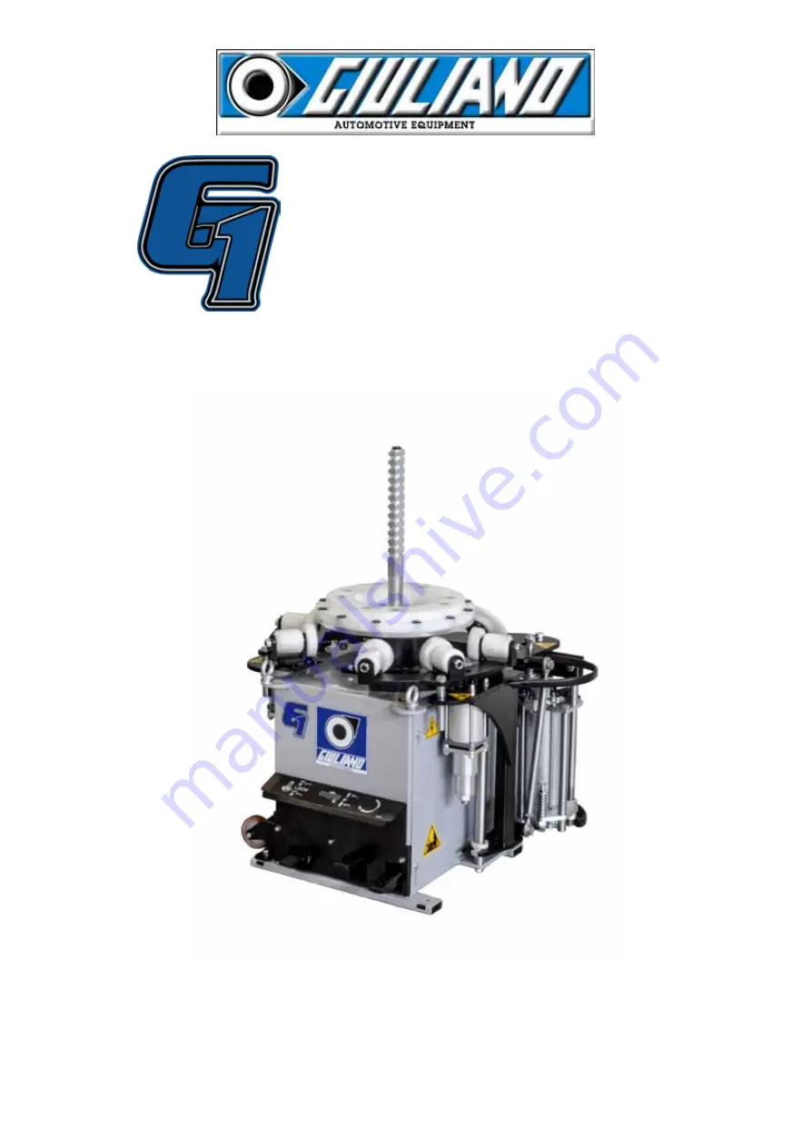
background image

Original Instructions

Operation Instructions

Ed.07/14  Cod.3038988

English

G1 SPORT

SPORT

Summary of Contents for G1 SPORT

Page 1: ...Original Instructions Operation Instructions Ed 07 14 Cod 3038988 English G1 SPORT SPORT ...

Page 2: ...ponsibility that the product which this statement refers to meets the following directive Passenger Car Tyre Changer Raccolta differenziata 86 217 CEE 2006 42 CE 2006 95 CE 2004 108 CE G1 SPORT G1 SPORT GIULIANO INDUSTRIAL S p A Il Presidente CdA Gianluca Maselli GIULIANO INDUSTRIAL S p A Il Presidente CdA Gianluca Maselli GIULIANO INDUSTRIAL S p A Il Presidente CdA Gianluca Maselli Correggio 24 0...

Page 3: ... 9 1 Tyre Changer site requirements 9 9 2 Tyre Changer placement and connections 9 10 0 EQUIPMENTCOMPONENTS 10 11 0 CONTROLS DESCRIPTION 11 12 0 TYRE DEMOUNTING 12 13 0 TYRE MOUNTING 13 14 0 STANDARD ACCESSORIES 14 15 0 RE POSITIONING 15 16 0 STORAGE 15 17 0 SCRAPPING 15 18 0 OIL TREATMENT 15 19 0 MAINTENANCE 16 19 1 Standard maintenance 16 19 2 Extraordinarymaintenance 16 20 0 TROUBLESHOOTINGCHAR...

Page 4: ...re Changer data on Data Plate and this Manual please refer to Tyre Changer data plate only 1 2 Manufacturer data Please check the Declarations of Conformity at page 2 of this Manual and Tyre Changer Data Plate 1 3 Data plate Keep this Manual in good conditions for further references Keep all instructions permanently with the unit 2 0 GENERAL DESCRIPTION The Tyre Changer is NOT intended for demount...

Page 5: ... Maximum wheel diameter 25 640mm Motoinverter chuck details Motor power 0 75 Kw Maximum torque 1200 Nm Clockwise rotation speed 8 16 rpm Working noise level 70 dB Layout details Minimum overall dimensions 975 x 750 x 980 H mm Net weight accessories excluded 195 kg Operating temperature range min 5 C max 50 C 41 122 F Standard accessories ref page 14 Bead Breaker Tool Bead Breaker Disc Tool Push Wh...

Page 6: ...ediately in case of damage or loss Do not operate the Tyre Changer in case of warning labels lack Do not hide any warning label by any mean Refer to the above mentioned codes for warning labels ordering Code 3038989 Code 3025916 Code 3025916 Code 3025916 Code 3031393 Code 3031393 ...

Page 7: ... of using the machine shall not be under the influence of drugs alcohol or other substances which could compromise their physical and mental work capabilities For higher safety operators shall wear health safety footwear gloves protection goggles and shall NOT wear any form of clothing that could get caught up or restrict the operator s movements The operator must be able to read and ensure full c...

Page 8: ... remove all fixing screw and free the Tyre Changer from its original pallet Check the perfect condition of the machine making sure that no part is damaged or missing referring to the picture at page 10 If in doubt please do not use the machine and get in touch with your Distributor for further steps Keep packing elements away from children All packing elements must be stored in the proper stocking...

Page 9: ...ted by machine s data label Even small jobs done on the electrical system must be carried out by professionally qualified personnel The Manufacturer is not responsible for damages caused by electrical connection different from the original indications The pneumatic network of the installation area must be provided with min 8 bar working pressure outlet Connect the machine to the pneumatic network ...

Page 10: ...OMPONENTS Transport Wheel Pedal control unit Roller Bead Breaker Disc Centre plate Antirotation Pin Roller Bead Breaker Tool Bead Lifting Lever Bead Breaker Disc Exagonal Blocking Device A Cones Exagonal Blocking Device B ...

Page 11: ...ted with no tyre onto the machine Mind any component which could interfere with machine testing operations 1 Lock On Off Antirotation Pin ref 5 2 Roller movementmand bead breaker 3 Clockwise and anti clockwise centre plate ref 4 rotation pedal control 2 4 5 ...

Page 12: ... disc lever for bead breaking the tyre fig 4 Insert the bead lifting lever ref 8 fig 5 under the bead over the rim board and block it in the exagonal blocking device fig 3 fig 4 fig 5 Push the roller pedal ref 2 fig 6 to activate the roller bead breaker and subsequently press the motor pedal ref 3 to demount the wheel Repeat the movement fig 5 for the second bead For remove the wheel push the roll...

Page 13: ...ons at page 12 To mount the tyre on rim insert both bead brea king tools before positioning the tyre fig 2 Insert the tyre side and push the motor pedal to rotate the centre plate fig 2 fig 2 When the wheel is in the correct position push with one hand on tyre and with another hand hold the bead breaker tool Press the motor pedal ref 3 to rotate the centre plate fig 3 fig 3 When the first rotation...

Page 14: ...14 14 0 STANDARD ACCESSORIES Bead Breaker Tool A Bead Lifting Lever Bead Breaker Tool B Exagonal blocking devices A and B Cones ...

Page 15: ... Federal regulations Clean up the oil and send to special disposal centres according to current National regulations 18 0 OIL TREATMENT OIL IS HIGHLY POLLUTANT Do not throw away outdoors or pour on the ground To re position the Tyre Changer in a new workplace secure the moving parts i e the bead pressing arms etc discon nect all the power sources and install it again following all the instruction ...

Page 16: ...o grant the correct functioning of all centering and locking systems Do not clean with compressed air which can blast dirt between moving parts Every 2 3 days check the oil dropping into the cup 1 drop every 4 5 activa tions of the bead pressing tool or of the bead loosening systems If necessary turn the screw on the top of the cup by a screwdriver On periodical basis check the oil level which has...

Page 17: ...edal return spring broken or loosened 1 Adjust foot pedal 2 Check screws tightening or replace screws 3 Replace micro switch 4 Replace return spring Chuck rotating motor turns at one speed only or in one direction only 1 Micro switch damaged or defec tive 2 Micro switch cable unplugged 3 Motor damaged 4 Motor cables unplugged 1 Replace micro switch 2 Check and connect micro switch cable 3 Replace ...

Page 18: ...INE 230V 1Ph 50 60Hz Imax 16A Id 30mA 1 2 3 4 L N MOTOR 1HP U V W Plug and socket Molex Minifit SLOW SPEED CLOCKWISE FAST SPEED CLOCKWISE SPEED COUNTERCLOCKWISE WHITE GREY YELLOW BROWN MOTOINVERTER S1 S2 S3 PEDAL SWITCH 12V BROWN BLACK BLUE SWITCH FUNCTION S1 S2 S3 ELECTRONIC BOARD ...

Page 19: ...on 4192727 VALVE 2037489 BEAD BREAKER CYLINDER 4193998 VALVE 2037275 INTERNAL BEAD BREAKER CYLINDER 2038807 BEAD BREAKER VALVE 4192728 VALVE 2038847 VALVE AIR 2037549 CYLINDER ARM 4193997 VALVE 2037244 INTERNALE CYLINDER 2038806 LOCKING VALVE ...

Page 20: ... the machine The user must carry out both cleaning and greasing operations according to the instructions given in this manual Any operation concerning the replacement of parts is strictly reserved to authorized and trained staff Date Signature Intervention Replacements Notes Date Signature Intervention Replacements Notes Date Signature Intervention Replacements Notes ...

Page 21: ...21 Date Signature Intervention Replacements Notes Date Signature Intervention Replacements Notes Date Signature Intervention Replacements Notes Date Signature Intervention Replacements Notes ...

Page 22: ...GIULIANO INDUSTRIAL S p a Via Guerrieri 6 42015 Correggio RE ITALY ...

Reviews:

Related manuals for G1 SPORT