background image

Hepworth Heating Ltd.,

Nottingham Road, Belper, Derbyshire. DE56 1JT

General/Sales enquiries:

Tel: (01773) 824141  Fax: (01773) 820569

2000225228A.11.03

All replacement parts

All labour charges

All call-out charges

Thank you for installing a new Glow-worm appliance in your home.

Glow-worm appliances' are manufactured to the very highest standard so we are pleased

to offer our customers' a Comprehensive First Year Guarantee.

In the centre pages are to be found your Guarantee Registration Card, which we recommend you complete and

return as soon as possible.

If this card is missing you can obtain a copy or record your registration by telephoning the Heatcall Customer

Service number 01773 828100.

Our Guarantee gives you peace of mind plus valuable protection against breakdown by covering the cost of:

Guarantee Registration

Fanned Flue Boiler

This is a Cat I

2H

 Appliance

Reference in these instructions to British Standards and Statutory

Regulations/Requirements apply only to the United Kingdom.

For Ireland the current edition of I.S.813

"Domestic Gas Installations" must be used.

The instructions consist of three parts, User, Installation and Servicing Instructions, which includes the Guarantee Registration

Card.  The instructions are an integral part of the appliance and must, to comply with the current issue of the Gas Safety

(Installation and Use) Regulations, be handed to the user on completion of the installation.

T o   b e   l e f t   w i t h   t h e   u s e r

7319

Instructions for Use

Installation and Servicing

G.C. No. 41-047-49

REGISTER YOUR GLOW-WORM APPLIANCE

FOR 1ST YEAR GUARANTEE PROTECTION

CALL 0208 247 9857

Micron

60FF

Summary of Contents for Micron 60FF

Page 1: ...you peace of mind plus valuable protection against breakdown by covering the cost of Guarantee Registration Fanned Flue Boiler This is a Cat I2H Appliance Reference in these instructions to British Standards and Statutory Regulations Requirements apply only to the United Kingdom For Ireland the current edition of I S 813 Domestic Gas Installations must be used The instructions consist of three par...

Page 2: ...Notified body 0086 The CE mark on this appliance shows compliance with 1 Directive 90 396 EEC on the approximation of the Laws of the Member States relating to appliances burning gaseous fuels 2 Directive 73 23 EEC on the harmonization of the Laws of the Member States relating to the electrical equipment designed for use within certain voltage limits 3 Directive 89 336 EEC on the approximation of ...

Page 3: ... is carried out by a competent person To obtain service please call your installer or Heatcall Glow worm s own Service Organisation using the telephone number given on the front cover of these instructions Please be advised that the Benchmark logbook should be completed by the installation engineer on completion of commissioning and servicing Instructions for Use All CORGI Registered Installers ca...

Page 4: ...stic Gas Installations the current Building Regulations and reference should be made to the current ETCI rules for Electrical Installation In GB the following Codes of Practice apply BS4814 BS6798 BS5440Part1and2 BS5546 Part1 BS5449 BS6891 BS6700 BS7074 Part 1 and 2 BS7593 BS7671 In IE I S 813 BS5546 BS 5449 BS 7074 BS 7593 Manufacturer s instructions must not be taken as overriding statutory requ...

Page 5: ...egulations External wiring must be correctly earthed polarised and in accordance with the relevant standards In GB this is BS6891 In IE this is the current edition of I S 813 Domestic Gas Installations Connection of the boiler and system controls to the mains supply must be through a common isolator and must be fused 3A maximum This method of connection must be by a fused doublepoleisolatingswitch...

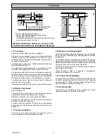
Page 6: ...efer to diagram 1 3 This boiler must be positioned so that at least the minimum operational and servicing clearances are provided Additional clearances may be required for installation If fixtures are positioned next to the boiler ensure access is provided for pipework installation At least a minimum clearance of 300mm from a permanently fixed surface must be left in front of the boiler for servic...

Page 7: ...and Ventilation 2 2 Flue Options There are various flue systems to choose from as follows Standard Top Outlet Flue Pack Pt No 230483 Easyfit Top Outlet Flue Pack Pt No 232057 Standard Rear Outlet Flue Pack Pt No 230482 Extended Top Outlet Flue Pack Pt No 230487 1 Metre Extension Kit Pt No 230484 A flue system up to 3 metres in length can be made by connecting 1 metre flue extension kits together O...

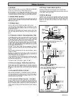
Page 8: ... return with the boiler thermostat set at MAX which is about 82o C 180o F The pressure loss of the boiler at 23 litre minute giving 11o C temperature difference is 300mm head of water High resistance microbore systems may require a higher duty pump 3 3 Bypass A bypass is usually unnecessary on systems using a 3 port diverter valve since one port will remain in the open position at alltimes Thisall...

Page 9: ...otal water system volume and the initial system design pressure For any system an accurate calculation of the vessel size is given in the current issue of BS7074 Part 1 Example For an initial system design pressure of 0 7bar the minimum total vessel volume required is 0 063xTotal System volume Note A higher initial design pressure requires a larger volume expansion vessel Guidance on vessel sizing...

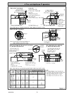
Page 10: ...may be joined together but the total flue system must not exceed 3 metres 44 5mm 52mm FLUE LENGTH MAX 840mm extd MAX 570mm std Easyfit FLUE LENGTH MAX 840mm extd MAX 570mm std Easyfit 15mm SCREW TAPE 4mm 140mm TOP OUTLET FLUE PACK Note Outer casing mounting brackets boiler details removed for clarity Note Outer casing mounting brackets boiler details removed for clarity X STD EXTD X plus 19mm RH 1...

Page 11: ...on the wall making sure that the minimum clearances are maintained see diagram 4 3 Mark the centre line position of the flue Top or Rear as diagram 4 3 Forasideflue extendcentrelineof Top toL H orR H corner Mark the position of the centre of the flue and boiler as diagram 4 3 4 4 Flue Hole Cutting Having marked out the flue centre cut a hole for the flue using preferably a 115mm minimum core drill...

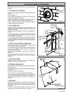
Page 12: ...o the outside wall is not practical the flue system can be installed from inside Use of the optional wall liner kit is required 4 8 Rear Flue Fixing Fit the self adhesive foam seal provided in the flue pack around the air duct at the position shown in diagram 4 1 Make sure that the ductings do not slope down towards the boiler Make good around the flue outside after installation of the boiler Impo...

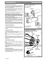
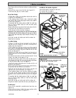
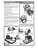
Page 13: ...ary to connect the flue spigot and gasket to the outlet using self tapping screws provided see diagram 5 6 Note The spigot would only be fitted to the top flue outlet where averticalfluekitorincertainfluebendorientationsisincorporated Instructions are supplied with these kits Lift the boiler into position hooking over the top mounting bracket Note Anti theft screw kits are available part no s 4581...

Page 14: ... Swing the air deflector out from right hand side the slot in air deflector allows you to do this to allow easy access to fitting fan assembly Note Apply soap to seals on flue duct extension piece to help it slide in be careful not to damage O ring Insert flue duct extension piece into top turret see diagram 5 7 Note Make sure that the flue duct extension piece is positioned so that the nibs are u...

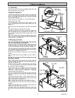
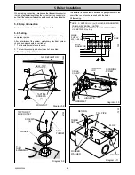
Page 15: ... internal wiring Using heat resistant 85o C cable of at least 0 75mm2 24 0 2mm and of a suitable length thread through the grommet at the rear of the control box through the cable clamp and connect to appropriate terminals Tighten cable clamp screws see diagram 5 10 Standard colours are brown permanent live Lp black switch live Ls blue neutral N and green yellow earth A switch live should be conne...

Page 16: ...ble as mains see diagram 5 10 5 9 Testing Checks to ensure electrical safety must be carried out by a competent person After installation of the system preliminary electrical system checks as below should be carried out 1 Test insulation resistance to earth 2 Test earth continuity and short circuit of all cables 3 Test the polarity of the mains Diagram 5 9 TOP TURRET 6793 GASKET SCREWS 4 TOP TURRE...

Page 17: ...erty or any electrical installation Release cold water to initial system design pressure The set pointer on the pressure gauge should be set to coincide with the indicating pointer 6 3 Initial Lighting and Testing CAUTION This work must be carried out by a competent person in accordance with the current issue of BS6798 Make sure that boiler case is fitted securely Make sure that all naked lights a...

Page 18: ...ain the required setting turning screw clockwise to decrease pressure see diagram 6 2 Replace cap Should any doubt exist about the gas rate check it using the gas meter test dial and stop watch at least 10 minutes after the burner has lit making sure that all other gas burning appliances and pilot lights are off ThegasratesshowninTable2areforguidanceonly dependent on the heat setting Turn the temp...

Page 19: ... a year should be enough Draw attention if applicable to the current issue of the Gas Safety Installation and Use Regulations Section 35 which imposes a duty of care on all persons who let out any property containing a gas appliance in the UK The user shall not interfere with or adjust sealed components It is the Law that servicing is carried out by a competent person Advise the user of the precau...

Page 20: ...tion chamber cover which is secured by two screws see diagram 8 3 Pull back electrode protection sleeve and disconnect electrode connection along with earth connection see diagram 8 6 Remove the burner retaining screw located at the right hand side of the burner see diagram 8 4 When completed take hold of burner and slide it to the left clearing the injector and remove Take care not to damage the ...

Page 21: ...t the functional checks as described in Section 6 9 1 Electrical Important On completion of the Service Fault Finding task which has required the breaking and remaking of the electrical connections the earth continuity polarity short circuit and resistance to earth checks must be repeated using a suitable multimeter Refer to Boiler Fault Finding see diagram 9 2 Fault Finding WiringDiagram seediagr...

Page 22: ...22 2000225228A 9 Fault Finding Diagram 9 2 10270 ...

Page 23: ...FF b b b N b SL bk PI PL Pn Pump Neutral Pl Pump Live y KEY bk BLACK br BROWN b BLUE p PURLPLE r RED y YELLOW gy GREY LED 1 LED 2 LED STATUS CONDITION RESET BURNER LIT Alternating Simultaneous Simultaneous Simultaneous Ignition Lockout Software Error Software Sequence Error Lighting Sequence Fan APS Lighting Sequence Thermistor Reversed Polarity Other Errors PCB Failure Burner Lit Non Volatile Loc...

Page 24: ... TO TERMINAL BLOCK PUMP NOTE A switch live Ls should be connected from an external control If no external control is available insert a link between Lp Ls 9 Fault Finding Diagram 9 5 10274 Does pump continue to run after SL is interrupted YES Does pump stop after several minutes System satisfactory NO YES YES NO Does the pump run when SL is applied Pump Overrun Operation Diagram 9 4 NO Faulty PCB ...

Page 25: ...e fan assembly see section 5 3 Unscrew the plastic R clips which retain all leads at the rear of boiler Removetheretainingwireandwithdrawtheelectricalthermistor from its phial see diagram 10 2 Remove thermistor lead from the plastic R clips at rear of case and the cable clips these are located down left hand side of boiler Draw thermistor lead followed by thermistor out through the case grommet Re...

Page 26: ...n the left hand side Support the multifunctional control remove the four extended screws from the flanged connection at the right hand side Remove and discard the original O ring from the flanged connection and fit the new O ring supplied into recess before fitting the replacement multifunctional control Afterassembly testforgas soundnessandpurgeinaccordance with the current issue of BS6891 or in ...

Page 27: ...e the switch When fitting the replacement make sure that the plastic tubes arefittedasshownindiagram10 6andtheelectricalconnections are made as diagram 9 5 10 12 Fan Part No 227034 diagram 10 7 Refer to Section 5 3 Remove the electrical connections and disconnect the air tubes Note Remove the electrical connections by pulling insulation boots only If top outlet installation Remove air deflector or...

Page 28: ...E24962 227098 Fuse Diagram 10 3 278414 2000227135 Control board Diagram 10 3 227038 Safety temperature limiter Diagram 10 2 E24897 Because of our constant endeavour for improvement details may vary slightly from those in the instructions 11 1 Part Identification The part number and the diagram location will help to identify the part 11 2 Ordering When ordering any spare parts please quote the numb...

Reviews: