background image

METRA MAX

12

Analog-Digital Multimeter

Operating Instructions

3-348-820-02

18/6.17

Summary of Contents for METRA MAX 12

Page 1: ...METRA MAX 12 Analog Digital Multimeter Operating Instructions 3 348 820 02 18 6 17 ...

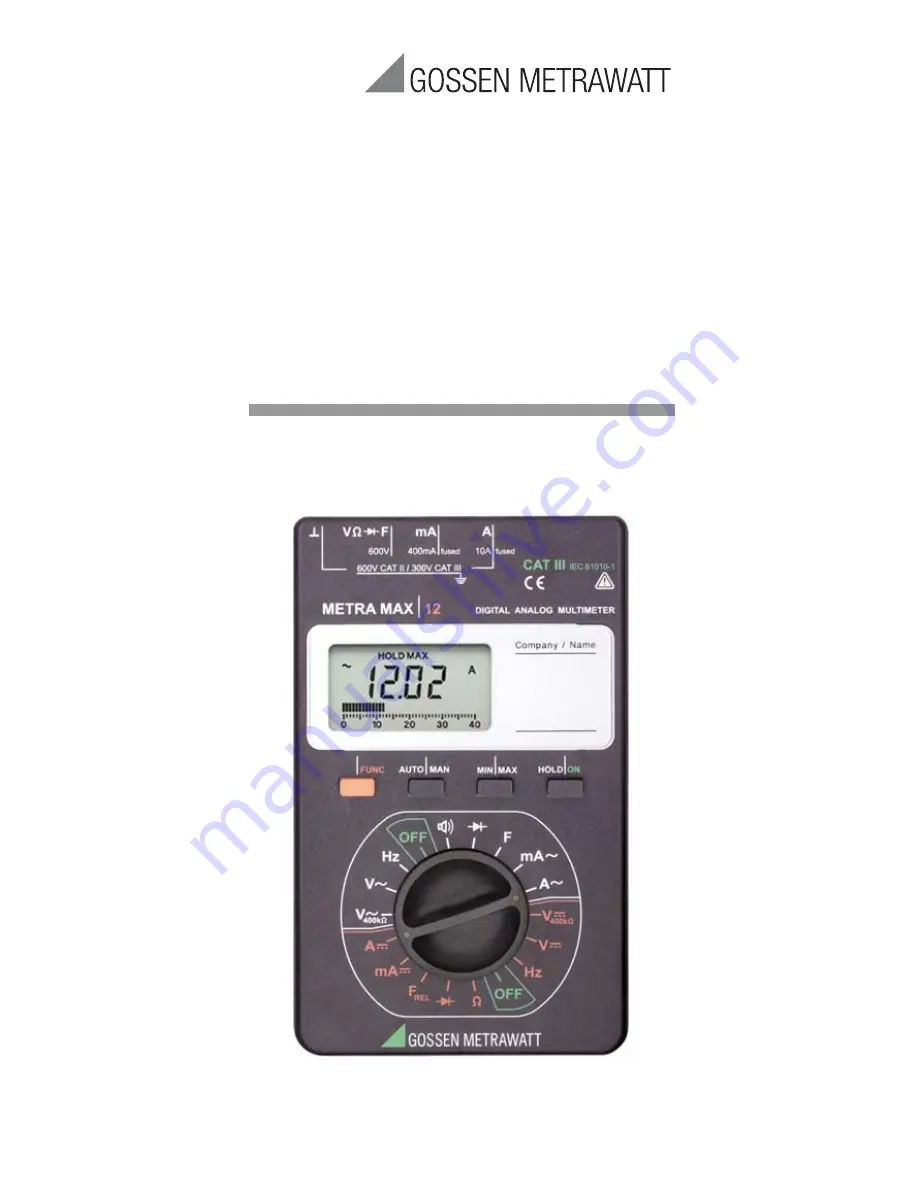
Page 2: ...u M mVA F HOLD MAX MIN 40 30 20 10 0 REL 5 F Hz mA A V V 400k OFF F V HOLD ON MIN MAX AUTO MAN Hz mA A OFF V MAN AUTO Hz k ni u M mVA F HOLD MAX MIN 40 30 20 10 0 REL 400k REL 2 5 1 3 4 7 6 FUNC mA 600V A V F 600 V CAT II 300 V CAT III 400mA fused 10A fused max 600 V ...

Page 3: ...l Measurement 7 Multifunction Key Display 1 Digital Display with Decimal Point and Polarity Indicator 2 Low Battery Display 3 REL HOLD and MIN and MAX Display 4 Continuity Test Display Loudspeaker symbol appears when acoustic signal is activated 5 Diode Measurement Display 6 Unit of Measure Display 7 Exceeded Measuring Range Display 8 Pointer for Analog Display 9 Analog Display Scale 10 Display fo...

Page 4: ...gnal 10 6 Measurement Value Storage HOLD 10 7 Storing Minimum or Maximum Values MIN MAX Hold 11 8 Voltage Measurement 12 9 Current Measurement 13 9 1 AC Measurement with Clip On Current Transformers 14 10 Continuity Testing and Resistance Measurement 15 11 Diode Testing 16 12 Capacitance Measurement 17 13 Frequency Measurement 18 14 Characteristic Values 19 15 Maintenance 23 15 1 Battery 23 15 2 F...

Page 5: ...only be operated by persons who are capable of recognizing contact hazards and taking the appropriate safety precautions Contact hazards exist anywhere where voltages of greater than 33 V may occur effective value Avoid working alone when taking measurements which involve contact hazards Be certain that a second person is present The maximum allowable voltage between any given connector jack 1 and...

Page 6: ...V may only be per formed with the safety cap applied to the test probe of the measurement cable For establishing contact in 4 mm jacks you have to remove the safety cap by levering out the snap lock of the safety cap with another sharp object e g the second test probe Electrical Safety of cable set KS17 2 CAT Definition I Measurements in electrical circuits not directly connected to the mains syst...

Page 7: ...ltage conducting parts may be exposed The instrument must be disconnected from the measuring circuit for repair replacement of parts or balancing If repair or balancing of a live open instru ment is required this may only be carried out by trained personnel who are familiar with the dangers involved Errors and Extraordinary Strains If it may be assumed that the instrument can no longer be operated...

Page 8: ... then back on If this pro cedure is unsuccessful briefly disconnect the battery from the contact terminals Attention Before opening disconnect the instrument from the measuring circuit and observe chapter 15 page 23 Automatic Shut Down Your instrument switches itself off automatically after 30 minutes if no keys or the selector switch have been activated during this time Switching the Instrument b...

Page 9: ...tion is deactivated if you press and hold the AUTO MAN key until you hear a second acoustic signal and the display switches from MAN to AUTO When switching back to automatic operation in the 400 mV range occurs the 4 V range is activated 3 4 Quick Measurements If you wish to perform quicker measurements than those possible with the automatic measuring range selection function the appropriate measu...

Page 10: ...moving coil mechanism is updated 20 times per second for V A and measurements This is especially advantageous for the observation of measure ment value fluctuations and for balancing 5 Acoustic Signal The following sequence steps are acknowledged by an acoustic signal New measurement function selection Activation or deactivation of the following functions AUTO MAN MIN MAX or HOLD A repetitive acou...

Page 11: ...priate with the multifunction key Select the measuring range manually Automatic mea suring range selection is not active in this mode Connect the device under test as described in the fol lowing measurement instructions Press the MIN MAX key HOLD MIN is displayed The measuring instrument con tinually updates and digitally displays the smallest occur ring measurement value This function remains act...

Page 12: ...e certain that the current ranges mA or A are deactivated and that the measurement cables are connected to the correct jacks V and before connecting your multimeter for the measurement of voltage If the fuse tripping limit values are exceeded due to operator error both the operator and the instrument are in dan ger Observe the voltage limit values as printed on the instrument Select the respective...

Page 13: ...s to the load component as shown without transition resistance Current Measurement Tips The instrument may only be used in power installations when the nominal voltage of the installation does not exceed 600 V The measuring circuit must be mechanically stable and protected against unintentional opening Conductor cross sections and connection points must be substan tial enough to avoid excessive ov...

Page 14: ...ransformer to the and mA or A jacks Some current transformers e g Z3511 3514 include safety devices which prevent dangerous voltage increases at open electrical circuits The maximum allowable operating voltage at the primary conductor is equal to the nominal voltage of the current transformer When reading the measurement value con sider the transformation ration of the transformer as well as addit...

Page 15: ...e measurement results Set the selector switch to Connect the DUT as shown Continuity Testing The instrument generates a continuous acoustic signal at a measured resistance of 0 approx 40 Resistance Measurement Press the multifunction key to switch to the resistance measuring range Display of the symbol is deactivated RX mA 600V A V F 600 V CAT II 300 V CAT III 400mA fused 10A fused ...

Page 16: ...orward voltage in volts As long as the voltage drop does not exceed the maximum display value of 3 000 V you can test several elements connected in series or reference diodes with small reference voltages Reverse Direction or Interruption The measuring instrument displays a voltage of approx 3 V battery voltage test Note Resistors and semiconductor paths in parallel to the diode distort the measur...

Page 17: ...es Only digital display is available in this mode Zero Adjustment relative mode For the measurement of small capacitive values in the 4 nF and 40 nF ranges the inherent capacity of the measuring instrument and the cables can be eliminated with zero bal ancing Connect the measurement cables to the measuring instrument without a DUT Press the multifunction key briefly The instrument acknowledges zer...

Page 18: ...the AUTO MAN key is required for sensitivity selection Apply the measurement magnitude in the same fashion as for voltage measurement Select sensitivity with the AUTO MAN key You can switch between sensitivity levels of 0 1 V 1 V and 10 mV After each activation of the AUTO MAN key the corre sponding sensitivity level is displayed After selection of this function with the selector switch the trigge...

Page 19: ...4 000 V 1 mV 11 M 400 k 40 00 V 10 mV 10 M 400 k 400 0 V 100 mV 10 M 400 k 600 V 1 V 10 M 400 k Voltage Drop at Maximum Measuring Current approx A 40 00 mA 10 A 450 mV 400 0 mA 100 A 1 5 V 10 00 A 10 mA 750 mV A 40 00 mA 10 A 450 mV 400 0 mA 100 A 1 5 V 10 00 A 10 mA 750 mV Open Circuit Voltage 400 0 100 m approx 0 5 V 4 000 k 1 40 00 k 10 400 0 k 100 4000 k 1 k 40 00 M 10 k 400 0 100 m 3 000 V 1 ...

Page 20: ... 600 V effective continuous 4 000 V 0 5 2 40 00 V 400 0 V 600 V V V 400k 400 0 mV 1 5 5 600 V effective continuous 4 000 V 1 5 40 00 V 400 0 V 600 V 1 10 A 40 00 mA 0 8 2 480 mA continuous 400 0 mA 10 00 A 3 1 5 5 3 3 A 40 00 mA 1 5 480 mA continuous 400 0 mA 10 00 A 3 2 5 3 3 400 0 0 8 5 600 V effective 5 min 4 000 k 0 8 2 40 00 k 400 0 k 4000 k 1 5 40 00 M 2 5 400 0 Acoustic signal for 0 40 3 00...

Page 21: ...eld 50 mm x 30 mm with analog and digital display and display of unit of measure current type and various special functions Analog Display LCD scale with bar graph pointer Scale Length 40 mm Scaling 0 40 with 40 graduations Polarity Display with automatic switching Overflow Display Bar with triangle Measuring Rate 20 measurements s Digital Display Char Height 7 segment digits 10 mm Number of Place...

Page 22: ... 21 C and 25 C 40 C V 0 1 x intrinsic uncertainty K V A A F Hz Influence Variable Influence Range max resolution Frequency Inherent Uncertainty at Ref of rdg D Frequency VAC 4 40 400 V 20 Hz 50 Hz 50 Hz 500 kHz 2 3 400 mV 600 V 20 Hz 50 Hz 50 Hz 100 Hz 2 3 Influence Variable Influence Range Meas Magnitude Measuring Range Influence Effect Relative Humidity 55 75 V A F Hz 1x intrinsic uncertainty In...

Page 23: ...er IEC 61010 1 2010 DIN EN 61010 1 2011 VDE 0411 1 2011 Electromagnetic Compatibility EMC Interference Emission EN 61326 1 2013 Class B Interference Immunity EN 61326 1 2013 EN 61326 2 1 2013 Mechanical Design Protection Housing IP 50 Connector Jacks IP 20 Dimensions W x H x D 92 mm x 154 mm x 25 mm Weight approx 0 2 kg with battery 15 Maintenance Attention Disconnect the instrument from the measu...

Page 24: ...tween the cells before clos ing the housing in order to prevent pinching of the cables Replace the housing base and press until it snaps audi bly into place Dispose of the dead battery in an environmentally sound fashion 15 2 Fuses The 16 A fuse interrupts the 10 A current measuring range and the 1 6 A fuse the mA current measuring ranges All other measuring ranges continue to function If a fuse b...

Page 25: ...ial maintenance is required for the housing Exces sive contamination has an adverse effect on isolation and reduces input resistance The surface must be kept clean for this reason Use a slightly dampened cloth for cleaning Avoid the use of cleansers abrasives or solvents Device Return and Environmentally Compatible Disposal The instrument is a category 9 product monitoring and control instrument i...

Page 26: ...ss a calibration interval of 2 3 years is usually sufficient During recalibration in an accredited calibration laboratory DIN EN ISO IEC 17025 the deviations of your instrument in relation to traceable standards are measured and docu mented The deviations determined in the process are used for correction of the readings during subsequent application We are pleased to perform DAkkS or factory calib...

Page 27: ...ance frequency and temperature Competent Partner GMC I Messtechnik GmbH is certified in accordance with DIN EN ISO 9001 Our DAkkS calibration laboratory is accredited by the Deut sche Akkreditierungsstelle GmbH National accreditation body for the Republic of Germany in accordance with DIN EN ISO IEC 17025 under registration number D K 15080 01 01 We offer a complete range of expertise in the field...

Page 28: ... to change without notice A pdf version is available on the internet GMC I Messtechnik GmbH Südwestpark 15 90449 Nürnberg Germany Phone 49 911 8602 111 Fax 49 911 8602 777 E Mail info gossenmetrawatt com www gossenmetrawatt com ...

Reviews: