NT-Evolution 2.0 Installation Guide
1
Installation Review
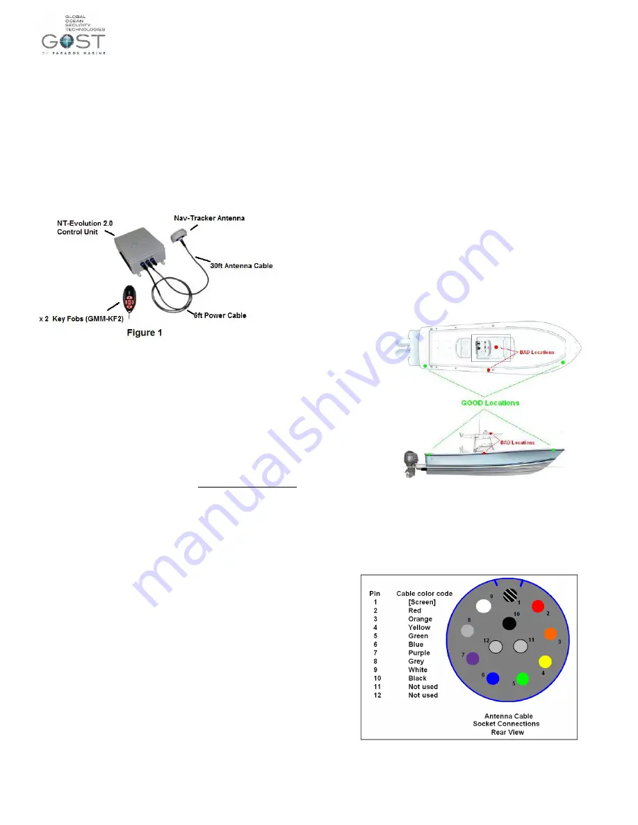
The NT-Evolution 2.0 brings many of our popular wireless sensing and
switching capabilities together with our proven tracking systems. It is
exclusively designed to defend High End go fast boats. The included
components are outlined below. Additional wireless sensors and relays can be
preprogrammed to the system as well. The NT-Evolution includes the Nav-
Tracker Antenna, NT-Evolution 2.0 Control Unit, 30ft Antenna cable, 6ft
Power cable, antenna mounting L-Bracket, two preprogrammed Key Fobs,
and any combination of preprogrammed sensors. As an added bonus, the NT-
Evolution 2.0 has the ability to send messages via cellular voice calls and sms
when in cellular coverage*. *The owner/operator must supply a GSM sim
card on a voice/sms plan if they want to utilize this feature, see page 3-5.
Voltage Requirements
Input Voltage: 10-32VDC
Short Circuit protection: Thermally Fused
Average Current Draw @ 12VDC when battery backup is charged = 120mA
Average Current Draw @ 12VDC when battery backup is charging = 800mA
Time to Charge battery backup: Approximately 5 hours
*Do not use a switched power supply that is normally left off when the
boat is idle. Keep a charge to the vessels battery banks whenever
possible.
All Zones, Outputs, + Key fobs are preprogrammed to your system.
Follow the instructions that come with each individual sensor or output
for their installation specifics. No programming is necessary on this
system.
Zone 1 - ______________ Output
’
s -
1, 2, + 3 are used (don
’t change)
Zone 2 ______________ Output 4 ________________________
Zone 3 ______________ Output 5 ________________________
Zone 4 ______________ Output 6 ________________________
Control Unit Locations
The Control Unit provides the logic for all the wireless zones, outputs, and
keyfobs while supplying a full battery backup to the tracking antenna in the
event that input voltage is lost. Consider the following when deciding on a
location:
Keep it accessible but not visible. The Enclosure is IP67 rated,
though it is best not to mount it in an exposed area where it is more
susceptible to water spray or tampering
Common Places on a Center Console are inside behind the
Electronics
If the Vessel has a forward berth, inside and behind storage spaces
is common.
Keep it hidden as best as possible as if thieves cut the battery
supply cable, the battery backup in the control unit is the last line
of tracking power supply for the antenna.
The cover may have to be removed for yearly maintenance, make
sure that it is accessible.
Antenna Location Considerations
Think Security. The location of the antenna is critical to proper
system operation and should be toughly scrutinized.
The antenna is able to penetrate up to
½ inch of solid fiberglass,
making way for covert installs.
Locate the antenna a minimum of two feet away from metallic
obstructions such as hand rails, rod holders and cleats.
Choose a location that is not directly under or near radar arrays to
prevent possible interferences.
Make sure that the underside of the antenna is accessible to
connect the antenna cable. Leave approximately four inches
directly underneath the antenna to provide space for the
connection.
Mount on a flat horizontal surface.
The antenna communicates its data to the Inmarsat
® Geostationary
based satellite network. As a general rule, a clear line of site
towards the equator is needed.
Center Consoles - It is suggested that the antenna not be installed
on T-Tops as they are more vulnerable for tampering. Popular
locations include forward/aft stringers underneath the gunwale.
Keep away from midship gunwale mounting as the T-Top could
potentially block the signal from getting out. Figure 1.
Whenever possible, dry run the installation procedure and test the
location beforehand. See Installation #6
Figure 2
Installation
1.) Thoroughly read the Nav-Tracker antenna location considerations
and mount the antenna according to this criterion.
2.) To assist the installer with the antenna wire run, the antenna cable has one
end with a connection and the other with ten sockets protected by heat shrink.
Snake the cable from antenna to the control unit, remove the heat shrink, and
connect the pin arraignment at the control unit according to Figures 3+4.
Figure 3


