background image

1

Governors America Corp. © 2020 Copyright All Rights Reserved

ESD2300 Series Speed Control Unit  9-2020-A2    PIB4138 

ESD2300 Series

Speed Control Unit

2

SPECIFICATIONS

RELIABILITY

Vibration

5 g @ 20-500 Hz

Testing

100% Functionally Tested

ENVIRONMENTAL

Ambient Temperature

-40° to 85 °C (-40 ° to 180 °F)

Relative Humidity

up to 95 %

All Surface Finishes

Fungus Proof 

and Corrosion Resistant

PHYSICAL

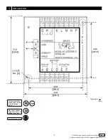
Dimension

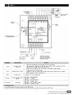
See Wiring Diagram and Outline

Weight

1.2 lbf (0.544 kgf)

Mounting

Any position, Vertical Preferred

COMPLIANCE / STANDARDS

Agency

CE and RoHS Requirements

1

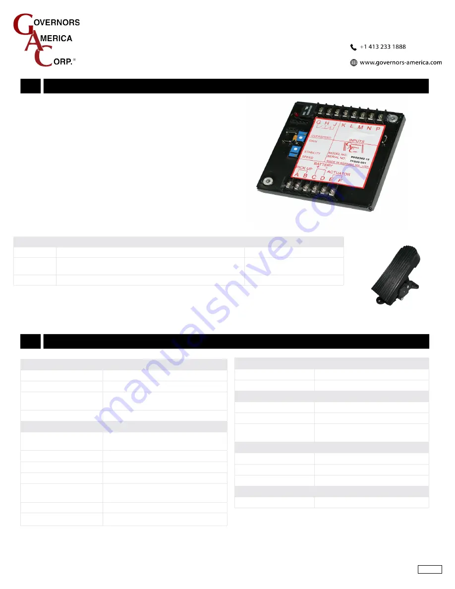
The ESD2300 Series speed control unit is an electronic speed control 

device designed to control engine speed with fast and precise response 

to transient load changes. This closed loop control, when connected 

to a proportional electric actuator and supplied with a magnetic speed 

sensor signal, will control a wide variety of engines in an isochronous 

or droop mode. It is designed for high reliability and hard potted to with-

stand the engine environment.

• 

12 V DC 

• 

Variable Speed Control

• 

Adjustable PID Functions

• 

Foot Pedal and Installation Kit

• 

Single Element Speed Switch

PERFORMANCE

Isochronous Operation

± 0.25 % or better

Speed Range / Governor

1 - 7.5 KHz Continuous

Speed Drift with Tempera-

ture

Typically < +0.5 %

Idle Range

500 to 5000 Hz with trim pot installed

INPUT / OUTPUT

DC Supply Nominal

12 V DC; 8-20 V DC

Transient and Reverse Voltage Protected

Polarity

Negative Ground (Case Isolated)

Power Consumption

60 mA continuous plus actuator current

Speed Signal Range

0.5 - 50 V AC

Actuator Current Range

@ 77° F (25 °C)

MIN 2.5 A

MAX 10 A

Speed Sensor Signal

0.5 - 50 V AC RMS

PRODUCT

DESCRIPTION

USE WITH FOOT PEDAL

ESD2349-12

12 V DC, Off Road, Variable Speed, Horizontal Foot Pedal

FP100

ESD2351-12

12 V DC, supports Horizontal and Vertical Foot Pedals

FP201* (Vertical) 

FP202** (Horizontal)

ESD2352-12

12 V DC, configured for use with Morse Foot Pedal

Not supplied by GAC

OVERVIEW

* Pedal with mounting hardware available as KT-FP201

** Pedal with mounting hardware available as KT-FP202

Summary of Contents for ESD2300 Series

Page 1: ...op mode It is designed for high reliability and hard potted to with stand the engine environment 12 V DC Variable Speed Control Adjustable PID Functions Foot Pedal and Installation Kit Single Element Speed Switch PERFORMANCE Isochronous Operation 0 25 or better Speed Range Governor 1 7 5 KHz Continuous Speed Drift with Tempera ture Typically 0 5 Idle Range 500 to 5000 Hz with trim pot installed IN...

Page 2: ... ESD2300 Series Speed Control Unit 9 2020 A2 PIB4138 3 INSTALLATION See Section 10 for more dimensions Mount in a cabinet engine enclosure or sealed metal box Vertical orientation allows fluids to drain in moist environ ments Avoid Extreme Heat Dimensions in mm ...

Page 3: ...ng C D Battery Power 12VDC 16 gauge 1 3 mm2 or larger wire Install a 15 amp fuse in the positive battery lead to protect against reverse voltage Battery positive input is Terminal C E F Actuator 16 gauge 1 3 mm2 or larger wire G H J Overspeed Shut Down System Terminal G Normally Open Terminal H Common Terminal J Normally Closed K Through P Foot Pedal Terminal K Supply Red Terminal L Sensor Signal ...

Page 4: ...tability persists adjust the next parameter STABILITY Follow the same adjustment procedure steps 1 3 as the GAIN pa rameter Normally adjustments made at no load achieve satisfactory performance If further performance improvements are required see Section 6 SYSTEM TROUBLESHOOTING Make sure the following adjustments are set before starting the engine GAIN Middle Position STABILITY Middle Position 5 ...

Page 5: ... while cranking 1 2 3 Short open in actuator device wiring Defective speed control unit Defective actuator device see your Installation Manual System Troubleshooting section If unsuccessful in solving instability contact GAC for assistance info governors america com or call 413 786 1888 Instability INSTABILITY SYMPTOM PROBABLE CAUSE OF ABNORMAL READING Fast Periodic The engine seems to jitter with...

Page 6: ...ck or replace battery 2 Momentarily connect Terminals A and F The device should move to the full fuel position 1 2 3 4 Device or battery wiring in error Device or linkage binding Defective device Fuse opens Check for short in device or harness Engine remains below desired governed speed 1 Measure the device output Terminals A B while running under governor control 1 2 If voltage measurements is wi...

Reviews: