background image

ti19609a

3A2854G

EN

Operation - Repair - Parts

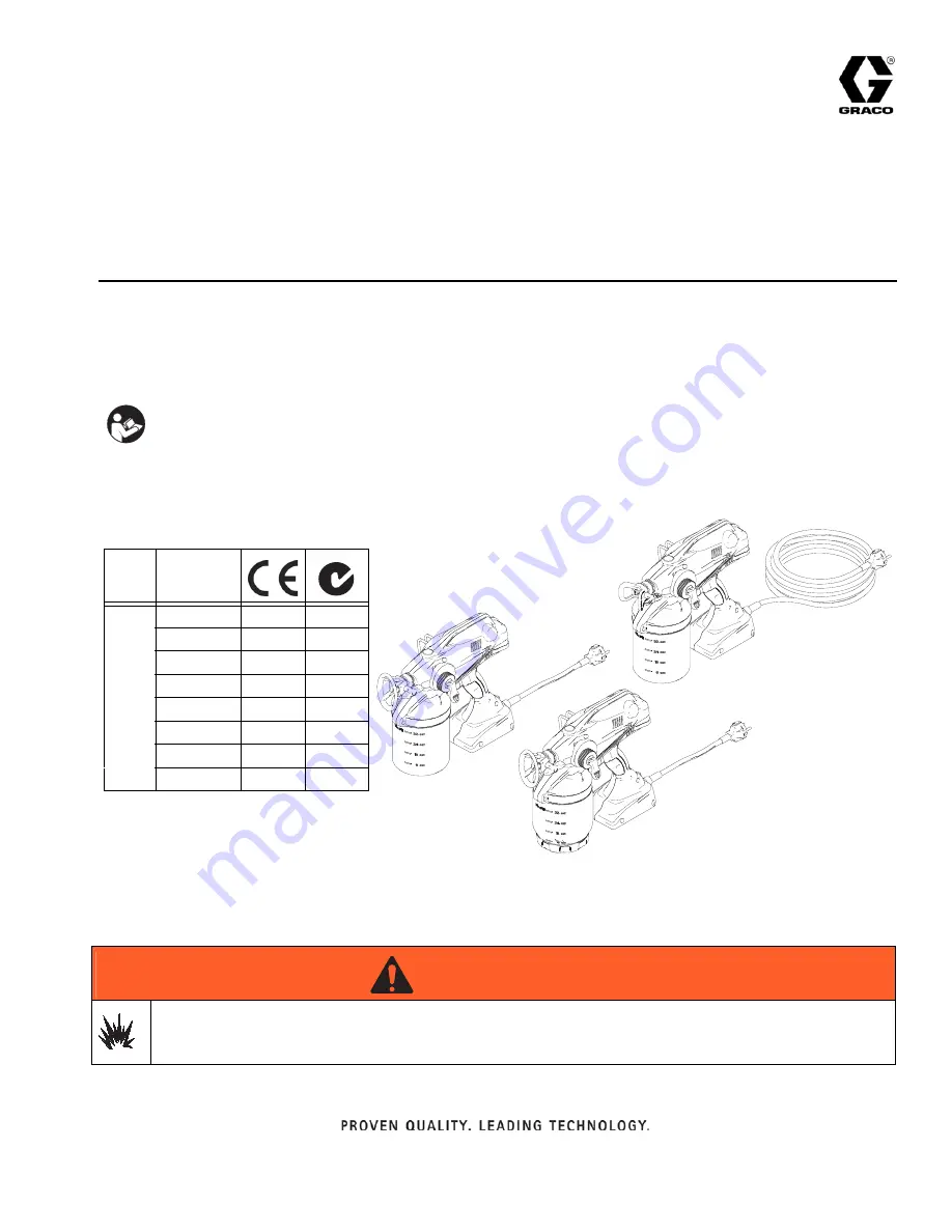
Electric Hand-Held Paint Sprayers

- For portable spray applications of architectural paints and coatings only

 -

- Not approved for use in explosive atmosphere locations -

All Models:

Maximum Working Pressure 2000 psi (14 MPa, 138 bar)

IMPORTANT SAFETY INSTRUCTIONS

Read all warnings and instructions in this 
manual. Save these instructions.

Model

230V

16N661

16N662

16N663

16N667

16P122

16W104

17C242

17C811

WARNING

WARNING

WARNING

WARNING

Use only water-based materials. 

Do not use materials which state “FLAMMABLE” on the packaging. For 

more information about your material, request MSDS from distributor or retailer.

Summary of Contents for 16N661

Page 1: ...imum Working Pressure 2000 psi 14 MPa 138 bar IMPORTANT SAFETY INSTRUCTIONS Read all warnings and instructions in this manual Save these instructions Model 230V 16N661 16N662 16N663 16N667 16P122 16W104 17C242 17C811 WARNING WARNING WARNING WARNING Use only water based materials Do not use materials which state FLAMMABLE on the packaging For more information about your material request MSDS from d...

Page 2: ...ata 29 Preferred Material Settings Log 30 Notes 31 Graco Standard Warranty 32 For the latest information about Graco products visit www graco eu 32 32 Important User Information Before using your sprayer read this Operation Manual for complete instructions on proper use and safety warnings Congratulations You have purchased a high quality paint sprayer made by Graco Inc This sprayer is designed to...

Page 3: ...ing wire to either power terminal The wire with insulation having an outer surface that is green with or without yellow stripes is the grounding wire Check with a qualified electrician or serviceman when the grounding instructions are not completely understood or when in doubt as to whether the product is properly grounded Do not modify the plug provided if it does not fit the outlet have the prop...

Page 4: ... before servicing equipment Connect only to grounded electrical outlets Use only 3 wire extension cords Ensure ground prongs are intact on power and extension cords Do not expose to rain Store indoors SKIN INJECTION HAZARD High pressure spray is able to inject toxins into the body and cause serious bodily injury In the event that injection occurs get immediate surgical treatment Do not aim the spr...

Page 5: ...ility MOVING PARTS HAZARD Moving parts can pinch or amputate fingers and other body parts Keep clear of moving parts Do not operate equipment with protective guards or covers removed Pressurized equipment can start without warning Before checking moving or servicing equipment follow the Pressure Relief Procedure in this manual Disconnect power TOXIC FLUID OR FUMES HAZARD Toxic fluids or fumes can ...

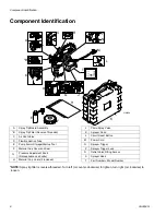
Page 6: ...Tip Guard Assembly B Spray Tip Filter Reverse Threaded C Air Vent Valve D Flexible Suction Tube E Pump Armor Storage Startup Tool F Material Cup Cover and Seal G Pressure Adjustment Knob Not available on all units H Material Cup Liners 5 included J Prime Spray Valve K Sprayer Case L Circuit Reset Button M Power Cord N Sprayer Trigger P Sprayer Trigger Lock R Outlet Valve Fitting Access S Sprayer H...

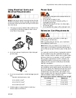
Page 7: ... sprayer draws A larger conductor number has a greater capac ity than a small one For example 7 5 mm2 conductor has a greater capacity than 1 5 mm2 conductor An undersized extension cord will result in a drop in line voltage and loss of power overheating and possible damage to equipment When using more than one extension cord make sure each individual cord contains at least the minimum con ductor ...

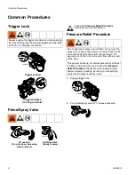
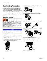
Page 8: ...is visible ti18913a ti18912a UP position For priming and releasing DOWN position Ready to spray ti14999a pump pressure ti16700a ti16701a Do not operate or spray near children Do not aim the sprayer at or spray any person or animal Keep hands and other body parts away from the discharge For example do not try to stop the paint flow with any part of the body This sprayer builds up an internal pressu...

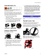
Page 9: ...noticeable by the sprayer sounding like it is slow ing down and will result ina poor spraying pattern To exit this mode turn pressure control knob down to lowest pressure setting that results in an acceptable spray pattern If spraying in low pressure range there may not be enough pressure to clear the plug Turn pressure control knob up to clear the plug Flexible Suction Tube This sprayer comes wit...

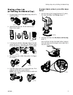
Page 10: ...o UP position then hold trig ger in for 10 seconds 3 Put prime spray valve DOWN to spray position 4 Reverse spray tip to UNCLOG position and trigger sprayer into a waste area for 10 seconds 5 Engage trigger lock and put prime spray valve UP to release pressure 6 Unscrew and remove material cup 7 Disengage trigger lock hold sprayer slightly above material cup and pull trigger to discharge fluid fro...

Page 11: ...ease 5 Put prime spray valve UP to release pressure Then rotate spray tip back to spray position NOTE Failure to perform this operation could result in poor spray pattern If sprayer fails to prime try one of the steps below 1 Use the Pump Armor storage startup tool to clean the inlet valve fitting See Storage page 17 2 Clean air vent holes See Shutdown and Cleaning page 15 Use a soft brush to clea...

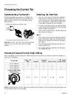
Page 12: ...e gun HINTS As you spray the tip wears and enlarges Starting with a tip hole size smaller than the maximum will allow you to spray within the rated flow capacity of the sprayer Tips wear with use and abrasive paint and need periodic replacement Do not spray with worn spray tips Poor spray pat tern quality will result Choosing Pressure Control Knob Setting Recommendations of a starting point for de...

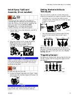
Page 13: ...n If material is pulsating you are moving too fast If material drips you are moving too slow See Trouble shooting page 25 Triggering Sprayer Pull trigger after starting stroke Release trigger before end of stroke Sprayer must be moving when trigger is pulled and released This equipment stays pressurized until pressure is manually relieved To help prevent serious injury from pressurized fluid such ...

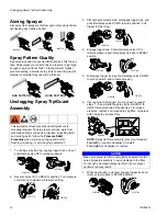
Page 14: ...o spray position and resume spraying 6 If spray tip is still clogged you may have to repeat steps 1 5 and rotate the spray tip from SPRAY to UNCLOG several times Repeat step 1 to release pressure remove and clean spray tip filter or replace with new spray tip assembly NOTE Spray tip filter assembly is reverse threaded Turn left or counter clockwise to install Turn right or clockwise to remove 7 Wh...

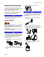
Page 15: ...ion tube strainer and orient as shown 6 Clean material cup if not using a liner and fill with water or appropriate flushing fluid NOTICE Failure to properly clean sprayer after each use will result in hardened materials damage to the sprayer and the warranty will no longer be valid Use only water based materials Do not use materials which state FLAMMABLE on the packaging For more information about...

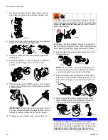
Page 16: ...spraying to prevent loss of fluid flow 14 Remove material cup and discard used fluid Use a soft brush to clean the black rubber inlet seal If vent holes become clogged use a paper clip to clear the holes 15 Remove spray tip guard assembly and clean with water or flushing fluid A soft brush can be used to loosen and remove dried material if needed ti18920a ti18913a ti16716a ti18912a ti14995a ti1499...

Page 17: ...eze cleaning bottle until Pump Armor flows out drain tube 5 Remove Pump Armor nozzle and replace child resistent cap and tighten securely for storage 6 Attach flexible suction tube and material cup Push valve DOWN to spray position 7 Store sprayer indoors in a cool dry place Store in an upright position only Never store sprayer with material in the cup NOTICE Failure to store sprayer with Pump Arm...

Page 18: ...arts Models 16N661 16N662 16N663 16N667 16P122 16W104 17C242 17Z811 50 3 51 52 53 23 22 21 20 1 2 54 55 17 17 16 15 14 13 12 11 19 18 6 7 8 9 10 24 25 32 34 50 31 58 30 29 28 27 26 37 33 36 35 40 41 59 32 38 47 42 43 44 45 7 60 61 5 23 ti21562b ...

Page 19: ... Assembly Kit includes parts 7 qty 2 8 9 All models 115478 Screw 10 All models 16M867 Complete Pump Assembly w Adjustable Prime Spray Valve includes parts 10 11 17 20 24 28 44 55 All models 16T447 Pump Housing Only includes parts 10 20 26 27 44 55 11 All models 262602 Inlet valve Repair Kit includes 11 12 13 12 All models 262602 Inlet valve Repair Kit includes 11 12 13 13 All models 262602 Inlet v...

Page 20: ...9 qty 2 31 33 34 44 50 55 58 Model 16N667 17C811 16T445 Motor Control Board Kit includes parts 20 29 qty 2 31 33 34 44 50 55 58 Models 16N663 16P122 24T887 Model 16W104 24W362 32 Models 16N663 16P122 16P465 Enclosure Replacement Kit includes parts 20 32 34 37 38 qty 10 39 44 55 Model 16N662 16P466 Enclosure Replacement Kit includes parts 20 32 34 37 38 qty 10 39 44 55 Models 16N661 16N667 16W104 1...

Page 21: ... 20 29 qty 2 31 33 34 44 50 55 58 Models 16N663 16P122 24T887 51 All models 24D425 Material Cup Cover includes parts 51 52 52 All models 16C650 Seal for Material Cup 53 All models 16D562 Cup Liner Replacement 10 pack 54 All models 24E377 Shoulder Strap 55 All models 16M945 Enclosure Clip 58 All models 115498 Ground Screw 59 Models 16N663 16N667 17C811 16R892 Cup Lip Brand Label 60 All models 16R88...

Page 22: ... with spring a on top of inlet valve fitting d Push inlet fitting up into pump cavity 2 Hold inlet in place and turn sprayer upside down Remove inlet valve fitting and visually check to see that inlet valve has seated correctly 3 Replace inlet fitting and use wrench to tighten to 10 ft lb 14 N m 4 Use a pencil or thin rod to lightly push on inlet valve to make sure it moves up and down freely Perf...

Page 23: ...ng are out of pump outlet cavity Installation 1 Screw outlet valve fitting into threads Use tool supplied and tighten to 8 ft lb 11 N m 2 Press outlet valve fitting access plug This equipment stays pressurized until pressure is manually relieved To help prevent serious injury from pressurized fluid such as skin injection splashing fluid and moving parts follow the Pressure Relief Procedure when yo...

Page 24: ... engage pressure control knob with retainer 5 Install washer onto pressure control knob 6 Install valve handle onto stem 7 Insert pin into valve handle Use pliers to press pin into hole NOTE If pin does not assemble repeat steps 3 6 to ensure pressure control is fully engaged with retainer IMPORTANT After assembly is complete perform the following steps to verify proper operation If sprayer fails ...

Page 25: ...tube is missing or improperly installed Make sure flexible suction tube is properly installed Flexible suction tube strainer or vent valve or vent holes are clogged See Shutdown and Cleaning page 15 Flexible suction tube o rings are damaged or missing Replace flexible suction tube o rings Flexible suction tube damaged Replace flexible suction tube Spray tip is not in SPRAY position Turn spray tip ...

Page 26: ...rvice page 22 Paint leaks from sprayer trigger area Pump has reached its maximum life Replace pump Problem Cause Solution Problem Cause Solution Spray pattern is pulsating Operator is moving too fast while spraying Slow speed of movement Spray tip or spray tip filter is clogged Unclog spray tip or clean spray tip filter page 14 Spray pattern has tails Pressure control knob is too low Turn up press...

Page 27: ...material has accumulated on spray tip guard assembly See Shutdown and Cleaning page 15 Spray tip filter is partially clogged or damaged Clean or replace spray tip filter See page 14 Spray tip guard assembly not threaded completely onto sprayer See Install Spray Tip Guard Assembly page 13 Seat is worn Replace spray tip Spray tip continues to drip or ooze material after trigger is released Needle as...

Page 28: ...08195 Sprayer is leaking fluid at Point B O ring on rear of needle assembly is worn out Replace o ring 108195 If 3 solutions above do not stop the leaking replace needle assembly kit Sprayer is leaking fluid at Point C Prime spray valve assembly is worn out Replace prime spray valve assembly Sprayer is leaking fluid at Points D Pump is worn out Replace bare or complete pump housing assembly Point ...

Page 29: ...ge Humidity Range 0 to 95 relative humidity non condensing 0 to 95 relative humidity non condensing Sound Pressure Level 70 5 dBa for sound power level add 81 5 dBa 70 5 dBa for sound power level add 81 5 dBa Vibration Level Acceleration Less than 2 2 feet s2 Less than 0 67 m s2 Power Cord 18 AWG 3 wire 18 in 18 AWG 3 wire 15 ft 1 0 mm2 3 wire 46 cm 1 0 mm2 3 wire 4 6 m Electrical Power Requiremen...

Page 30: ...Preferred Material Settings Log 30 3A2854G Preferred Material Settings Log Date Item Sprayed Material Sprayed Spray Tip Pressure Setting Mark Dial 03 24 2011 Crown molding Water based NAR311 EXAMPLE ...

Page 31: ...Notes 3A2854G 31 Notes ...

Page 32: ...ive to an authorized Graco distributor for verification of the claimed defect If the claimed defect is verified Graco will repair or replace free of charge any defective parts The equipment will be returned to the original purchaser transportation prepaid If inspection of the equipment does not disclose any defect in material or workmanship repairs will be made at a reasonable charge which charges...

Reviews: