


Repair - Parts
Air Powered, Heated, Plural Component Proportioner
For spraying polyurethane foam and polyurea coatings.
Not for use in explosive atmospheres.
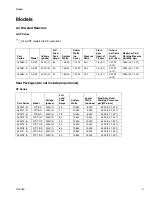
See page 3 for model information, including
maximum working pressure and approvals.
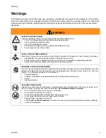
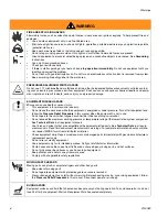
Important Safety Instructions
Read all warnings and instructions in this
manual. Save these instructions.
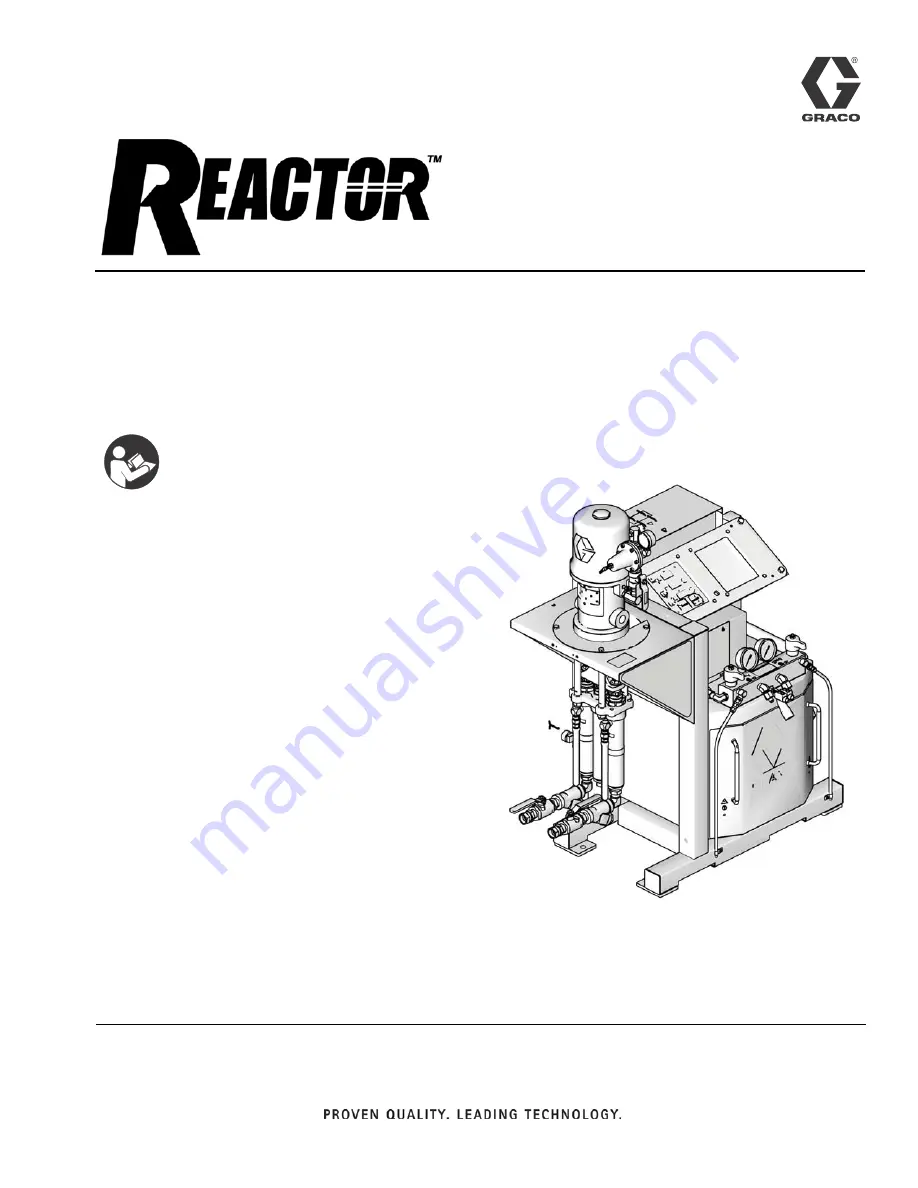
TI11252a
Model 259060 Shown
312408F
EN
For patent information, see
www.graco.com/patents.
Summary of Contents for Reactor HT Series
Page 43: ...Parts 312408F 43 ...