
3A7656C
EN
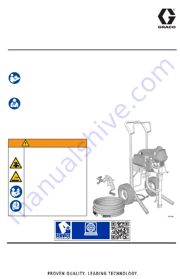
Operation, Repair, Parts
SaniSpray HP
™
130
Cart Airless Sprayer
For portable spraying of water-based disinfectants approved for spray application only.
Not for applying architectural paints and coatings. Not approved for use in explosive
atmospheres or hazardous (classified) locations. For professional use only.
Important Safety Instructions
Read all warnings and instructions in this manual, in related manuals, and on the unit
before using the equipment. Be familiar with the controls and the proper usage of the
equipment. Save these instructions.
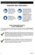
Important Medical Information
Read the medical alert card provided with the sprayer. It contains injection injury
treatment information for a doctor. Keep it with you when operating the equipment.
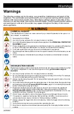
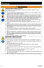
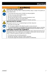
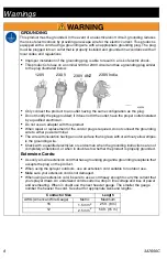
WARNING
CHEMICAL HAZARD
To prevent serious injury:
•
Follow all directions and
requirements on disinfectant
label. It is a violation of Federal
law to use an EPA-approved
disinfectant in a manner
inconsistent with its labeling.
•
Flush after each use. Never
store disinfectant in
equipment.
•
Use only with appropriate
personal protective
equipment.
www.graco.com/techsupport
??
??
Use only genuine Graco replacement parts.
The use of non-Graco replacement parts may void warranty
.


