
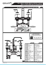
See fig. 2
Insert spout
(1)
with shank
(3)
through the central hole in the deck. Center spout over
side hole of mounting surface.
Insert the lift rod
(2)
into the hole of the spout base.
From underneath the sink place rubber washer
(4)
, metal washer
(5)
on the shank
(3)
,
then screw on the mounting nut
(6)
. Hand tighten only.
Make sure that the spout is in proper position on the sink. Tighten the mounting nut
(6)
using adjustable wrench.
Insert nozzle
(8)
and seal o-ring
(7)
into T-connection
(9)
.
Screw on the T-connection
(9)
onto spout shank as shown in fig.1 firmly but do not
overtighten.
Ver el dis. 2
Inserte el grifo
(7)
con tubo de conexión
(3)
a través del agujero central en la cubierta.
Centre el grifo en el agujero lateral de la superficie de montaje.
Inserte la varilla elevadora
(2)
dentro del agujero de la base del grifo.
Por debajo del lavabo coloque la arandela de goma
(4)
y la arandela de metal
(5)
en el
tubo de conexión
(3)
, luego enrosque la tuerca de montaje
(6)
. Apriete únicamente a mano.
Asegúrese de que el grifo se encuentra en la posición apropiada en el lavabo. Ajuste la
tuerca de montaje
(6)
usando la llave inglesa.
Inserte el inyector
(8)
y el sellador del anillo
(7)
en la conexión „T”
(9)
.
Ajuste firmemente la conexión „T”
(9)
sobre el tubo de conexión según lo demostrado en
la dis.1, pero no apriete demasiado.
~
ESPANOL
ENGLISH
SPOUT INSTALLATION
INSTALACIÓN DEL GRIFO
2
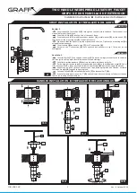
HANDLES INSTALLATION
INSTALACIÓN DE LAS MANILLAS
3
1
6
3
7
8
9
2
4
5
A
11
12
13
15B
14
11
12
13
IOG 2061.00
Rev. 4 October 2009
3
10.1
10B
15B
co
a
u
d
n
r
te
ie
rc
u
lo
izq
ckw
la
ise
H
10B
2
3.1
3.2
3.3
3.5
3.4
Installation Instructions
Instrucciones de Instalación
TWO HANDLE WIDESPREAD LAVATORY FAUCET
GRIFO DE DOS MANILLAS DE EXTENSION
IOG 2061.00
Rev. 4 October 2009
6
ENGLISH
~
ESPANOL
7
CARE AND MAINTENANCE
l
CUIDADO Y MANTENIMIENTO
Your
Graff
faucet is designed and engineered in accordance with
Su grifo de la
Graff
esta diseńado y dirigido acuerdo
con los
the highest quality and performance standards. Be sure not to
estándares de funcionamiento y calidad más altos. Este
seguro no
damage the finish during installation. Care should be given to the
dańar las terminaciones del grifo durante la instalación.
Cuide el
cleaning of this product. Although its finish is extremely durable, it
producto manteniendolo siempre limpio. Aunque su acabado es
can be damaged by harsh abrasives or polish.
Never use
extremadamente durable, puede ser dańado por los abrasivos o
abrasive cleaners, acids, solvents, etc. to clean any
Graff
pulientes ásperos.
Nunca utilice limpiadores abrasivos, ácidos,
product. To clean, simply wipe gently with a damp cloth and
solventes, el etc. para limpiar cualquier producto de la
Graff
.
blot dry with a soft towel.
Para limpiar, simplemente use un pańo húmedo y seque con
una toalla suave.
ENGLISH
~
ESPANOL
WARRANTY
l
GARANT
Í
A
Warranty conditions and warranty registration card are outlined on a
Las condiciones de la garantía y la tarjeta del registro de la garantía
separate sheet.
se encuentran en una pagina separada.
All dimensions and drawings are for reference only. For details, please
refer to actual products.
Todas las dimensiones y dibujos sirven
ú
nicamente de referencia. Para
consultar detalles, ver los productos.
Installation Instructions
Instrucciones de Instalación
TWO HANDLE WIDESPREAD LAVATORY FAUCET
GRIFO DE DOS MANILLAS DE EXTENSION
ENGLISH
For easy installation of your
Para la instalación fácil de su grifo
GRAFF faucet you will need:
de la GRAFF usted necesitará:
to READ ALL the instructions completely before beginning,
LEER TODAS las instrucciones completamente antes de comenzar,
to READ ALL the warnings, care and maintenance information.
LEER TODA la información sobre las advertencias,
To complete the project, you should:
cuidado y mantenimiento.
gather the tools and all the parts you will need,
Para terminar el proyecto, usted debe:
prepare the mounting area,
recolectar las herramientas y todas las piezas que usted necesitará,
mount the faucet,
prepare el área para el montaje,
connect the supply lines,
monte el grifo,
finally test and flush the faucet.
conecte las líneas de fuente,
You should have the following tools:
finalmente pruebe y limpie el grifo con un chorro de agua.
adjustable wrench,
Usted debe tener las herramientas siguientes:
channel pliers,
llave ajustable,
®
Teflon tape,
alicates acanalados,
®
plumbers putty or caulking (silicone).
cinta adhesiva de Teflon ,
masilla o silicona.
~
ESPANOL
FLOW RATE INFORMATION
INFORMACIÓN DE INTENSIDAD DE FLUJO
Maximum flow rate: 2.2 GPM (8.3l/min.) at 60 psi (4.1 bar)
Flujo máximo 2.2 GPM (8.3l/min.) con 60 psi (4.1 bar)
ENGLISH
~
ESPANOL
IOG 2061.00
Rev. 4 October 2009
1
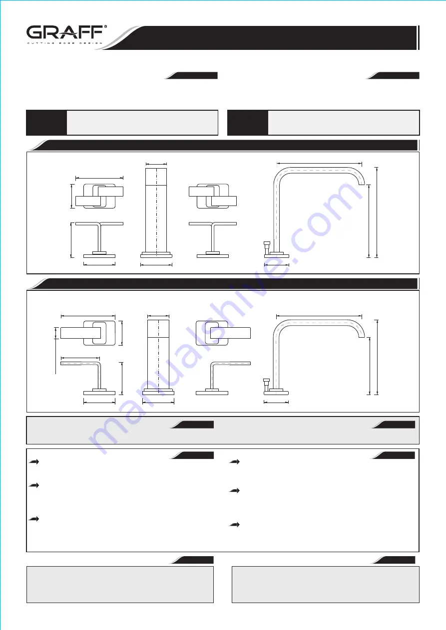
IMMERSION 2310-C9
Model
Modelo
IMMERSION 2310-LM40
Model
Modelo
ANTES DE LA INSTALACIÓN
Antes de instalar el grifo, es bueno ejuagar
las tuberías
suministro
para eliminar residuos.
R
ecomendamos el instalar los tapones
de filtro.
BEFORE INSTALLING
Before installing the faucet, it is good to rinse
the supply
pipelines in order to do away
with the dirty residues.
W
e recommend installing the filter taps.
ENGLISH
~
ESPANOL
6-49/64"
(172mm)
1-13/16"
(46mm)
5-37/64"
(139mm)
6-3/8"
(162mm)
3-35/64"
(90mm)
2-23/64"
(60mm)
2-23/64"
(60mm)
2-41/64"
(67mm)
1-13/16"
(46mm)
1-37/64"
(40mm)
Dear Customer
Estimado Cliente
Thank you for selecting our product. We are confident we can fully satisfy
Muchas gracias por elegir nuestro producto. Estamos seguros que podemos
your expectations by offering you a wide range of technologically advanced
satisfacer completamente sus expectativas ofreciéndole una amplia
variedad
products which directly result from our many years of experience in faucet
de productos tecnológicamente avanzados que resultan directamente de
and fitting production.
muchos años de experiencia en grifos y su producción apropiada.
ENGLISH
~
ESPANOL
For care, use soft towel with soap and water only! Under no
circumstances should you use any chemicals.
ATTENTION!
ATENCIÓN!
Para el cuidado, utilice solamente una toalla suave
con
jabón
y aqua!
Bajo ninguna circunstancia no use productos qu
í
micos.
Installation Instructions
Instrucciones de Instalación
TWO HANDLE WIDESPREAD LAVATORY FAUCET
GRIFO DE DOS MANILLAS DE EXTENSION
6-3/8"
(162mm)
1-13/16"
(46mm)
5-19/32"
(142mm)
4-19/64"
(109mm)
1-37/64"
(40mm)
2-23/64"
(60mm)
1-13/16"
(46mm)
2-7/8"
(73mm)
2-23/64"
(60mm)
2-7/16"
(62mm)
53/64"
(21mm)
4-1/16"
(103mm)
SET-UP DIAGRAM
DIAGRAMA DE INSTALACI
ÓN
1
ENGLISH
~
ESPANOL
SPOUT
LIFT ROD
CONNECTION PIPE
RUBBER PAD
STEEL WASHER
NUT
SEAL O-RING
NOZZLE
T-CONNECTION
HANDLE ASSEMBLY (right)
HANDLE ASSEMBLY (left)
VALVE EXTENSION
WASHER
FLANGED NUT
COUNTER NUT
RIGHT VALVE (with clockwise
opening cartridge)
LEFT VALVE (with counter-
clockwise opening cartridge)
CONE GASKET
WASHER
COUPLING NUT
HOSE 11-13/16” (300mm)
GRIFO
VARILLA ELEVADORA
TUBO DE CONEXIÓN
ARANDELA DE CAUCHO
ARANDELA DE METAL
TUERCA
SELLADOR DE ANILLO (O-RING)
INYECTOR
CONEXIÓN „T”
JUEGO DE MANILLA (derecha)
JUEGO DE MANILLA (izquierda)
EXTENSIÓN DE VÁLVULA
ARANDELA
TUERCA CON BRIDA
TUERCA DE CONTRA
VÁLVULA DERECHA (con cartucho
que se abre hacia la derecha)
VÁLVULA IZQUIERDA (con cartu-
cho que se abre hacia la izquierda)
JUNTA DE CONO
ARANDELA
TUERCA DE FIJACIÓN
MANGUERA 11-13/16” (300mm)
1
2
3
4
5
6
7
8
9
10
A
10B
11
12
13
14
15A
15B
16
17
18
19
IOG 2061.00
Rev. 4 October 2009
2
10B
1
3
4
5
6
2
10A
7
8
9
19
19
11
12
13
14
15B
15A
16
17
18
1
Installation Instructions
Instrucciones de Instalación
TWO HANDLE WIDESPREAD LAVATORY FAUCET
GRIFO DE DOS MANILLAS DE EXTENSION
Hot water inlet
Supply tube - 3/8" O.D. (9.5mm)
Entrada de agua caliente
Tuberia - 3/8" O.D. (9.5mm)
Cold water inlet
Supply tube - 3/8" O.D. (9.5mm)
Entrada de agua fr
í
a
Supply tube - 3/8" O.D. (9.5mm)
Flex hose
Flex tuberia
8"
(203.2mm)
MAX.1-1/2"
(
38mm)
MAX.
Ø
(Ø30mm)
1-3/16"
Ø1-1/2"
( 38mm)
Ø
15
/6
4"
(6
m
m
)
Ø1-1/2"
(Ø38mm)
4"
(101.6mm)
C9
LM40
4
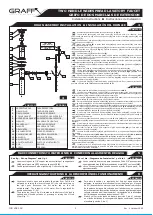
DRAIN ASSEMBLY INSTALLATION
INSTALACIÓN
DEL DRENAJE
~
ESPANOL
ENGLISH
PROTECTIVE CAP
DRAIN PLUG
DRAIN COLLAR
COLLAR GASKET
UNDER-BOWL GASKET
WASHER
FLANGED NUT
WASHER
DRAIN BODY
DISCHARGE PIPE
SEALING WASHER
BALL ROD
BALL ROD NUT
ADJUSTMENT PLATE
CLIP
SCREW
1
2
3
4
5
6
7
8
9
10
11
12
13
14
15
16
TAPA PROTECTORA
TAPÓN DE DRENAJE
COLLAR DE DRENAJE
EMPAQUETADURA SUPERIOR
EMPAQUETADURA INFERIOR
ARANDELA DE MONTAJE
TUERCA DE MONTAJE
ARANDELA DE TUBO
CUERPO DE DRENAJE
PIPA DE DESCARGA
ARANDELA SELLADORA
VARILLA DE BOLA
TUERCA DEL PIVOTE
PLATO DE AJUSTAMIENTO
BROCHE
TORNILLO
LIFT ROD
(
fig.1, item 2 )
Varilla elevadora
(
2
fig. 1)
1
2
3
4
5
6
7
8
9
10
14
11
12
13
15
16
~
ESPANOL
Desmontar las piezas del drenaje según lo demostrado en la
dis. 4
.
Inserte la empaquetadura superior
(4)
y el tapon del drenaje
(3)
en el agujero del
drenaje de un servicio. Colaque por debajo del lavatorio la empaquetadura inferior
(5)
en el
collar del drenaje
(3)
, la arandela
(6)
y tuerca de montaje
(7)
Coloque la empaquetadura inferior
(5)
correctamente debajo del servicio y entornille
a tuerca de montaje
(7)
firmemente pero no apriete demasiado.
Cerciorese de que la arandela de tubo
(8)
este en el cuerpo del drenaje
(9)
y entornille
el cuerpo del drenaje
(9)
en el collar del drenaje
(3)
apriete solamente con la mano
Preste atención en alinear el cuerpo del drenaje
(9)
de modo que el agujero horizontal
del cuerpo del drenaje esté en el mismo plano que la varilla elevadora
(dis.1, elem. 2)
. Apriete
el cuerpo del drenaje
(9)
sobre el collar del drenaje
(3)
y apriete la tuerca de montaje
(7)
.
Inserte el tapón de drenaje
(2)
en el collar del drenaje
(3)
.
Quite el clip de la abrazadera de muelle
(15)
del varilla de bola
(12)
; retire la tuerca
del pivote
(13)
del cuerpo, tome hacia fuera el arandela selladora
(11)
a lo largo del varilla de
bola
(12)
del extremo más.
Inserte el arandela selladora
(11)
y el varilla de bola
(12)
en un agujero lateral del
cuerpo del drenaje
(9)
. Asegúrese de que el extremo de la barra va debajo de la cabeza del tornillo
del tapón.
Ajuste la tuerca del pivote
(13)
serciorandose de que el
arandela selladora de la barra
(11)
y el varilla de bola
(12)
este instalado correctamente.
®
Enrrollar la cinta de Teflon para asegurar el pipa de descarga
(10)
, monte pipa de
descagra al cuerpo del drenaje
(9)
.
Levante el tapón de
renaje
(2)
a la posición de abierto, moviendo el varilla de bola
(12)
hacia abajo.
Inserte la varilla elevadora
(dis.1,
elem. 2)
por el agujero en el cuerpo del grifo
(dis. 1, elem.1)
y inserte el
plato de ajustamiento
(14)
. Ajuste a la altura apropiada y apriete el tornillo
(16)
.
Elija la posición del varilla de bola
(12)
en uno de los agujeros del
plato de ajustamiento
(14)
.
El varilla de bola
(12)
a través de la broche
(15)
y levante el
plato de ajustamiento
(14)
y despues el
segundo brazo de la broche
(15)
.
Intente cerrar con el tapón de drenaje
(2)
tirando de la varilla de elevación. Si no es
posible, haga las correcciones de la posición del
plato de ajustamiento
(14)
y de la barra
horizontal del el varilla de bola
(12)
.
d
ENGLISH
Dismantle the drain assembly to the parts shown on
fig.
4
.
Insert collar gasket
(4)
and drain collar
(3)
into drain hole of a lavatory. From
underneath the lavatory slip
under-bowl gasket
(5)
into drain collar
(3)
, washer
(6)
and
flanged nut
(7)
.
Position under-bowl gasket
(5)
correctly under the lavatory and screw flanged nut
(7)
firmly but do not
overtighten.
Make sure washer
(8)
is inside drain body
(9)
and screw drain body
(9)
onto drain
collar
(3)
hand tighten only.
Pay attention to align the drain body
(9)
so that the horizontal hole of drain body will
be
in the same plane as
a lift rod
(
2
fig.
1
)
. Tighten drain body
(9)
onto drain collar
(3)
and
tighten the flanged nut
(7)
.
Insert drain plug
(2)
into drain collar
(3)
.
Remove clip
(15)
from ball rod
(12)
; undo a ball rod nut
(13)
from body, take out
sealing washer
(11)
from
a nut and push the nut forward over ball rod
(12)
from the longer
end with the thread facing a ball.
Insert the sealing washer
(11)
and the ball rod
(12)
into a side hole of drain body
(9)
.
Make sure that the rod ending goes under the plug screw head.
Tighten ball rod nut
(13)
making sure that the ball rod seat
(11)
and ball rod
(12)
are
properly installed.
®
Add Teflon tape to tail tube
(10)
and mount tail tube to drain body
(9)
.
Lift the drain plug
(2)
to an open position, by lowering the horizontal ball rod
(12)
down.
Insert lift rod
(
2
fig.
1
)
down through
hole in the body of faucet
(1 fig.
1
)
and top of lift
rod strap
(14)
. Adjust to proper height and
tighten screw
(16)
.
Choose the position of horizontal ball rod
(12)
in one of the holes in lift rod strap
(14)
.
Insert horizontal ball rod
(12)
through one arm of spring clip
(15)
and lift rod strap
(14)
and
then second arm of spring clip
(15)
.
Try if a drain plug
(2)
closes the drain by pulling the lift rod. If not, make corrections of
position of lift rod strap
(14)
and horizontal ball rod
(12)
.
ENGLISH
~
ESPANOL
5
MAKE CONNECTIONS TO WATER LINES
CONECCION A LAS FUENTES DE AGUA
Use mounting set to 3/8” copper tubes consisting of cone gaskets
Use un completo de montaje para tuberias de Cu de 3/8” que consisten
(16)
metal washers
(17)
and coupling nuts
(18)
.
en empaquetaduras
(16)
las arandelas de metal
(17)
y uniones
(18)
.
Use adjustable wrench when tightening. Do not overtighten.
Utilice llaves ajustables cunado necesite ajustar alguna pieza. No
ajuste demasiado.
See fig. „Set-up Diagram” and fig. 1
Ve
r
el dis
. „Diagrama de
I
nstalación” y
el dis
. 1
6
OPERATING INSTRUCTIONS
LA DESCRIPCIÓN DEL FUNCIONAMIENTO
ENGLISH
~
ESPANOL
Levers are used to open and regulate the water flow. Full flow is
Para abrir la salida y la regulación del flujo del agua sirven las
obtained by turning the lever through 90° (the cold water tap on
palancas. La apertura total sucede al tornar la palanca por el ángulo
the right goes
clockwise, the hot water tap on the left
de 90° (de acuerdo con el movimiento de las manillas del reloj en caso
anticlockwise). The intensity of the water flow is regulated by
de la palanca del agua fría colocada en el lado derecho, en contrario
positions between 0°-90°.
del movimiento de las manillas del reloj en caso de la palanca del agua
The drain plug (item 2 fig. 4) situated on the bottom of the sink is
caliente colocada en el lado izquierdo). La regulación de la intensidad
opened and closed by means of pressing or raising the lift rod
del flujo de agua sucede en las posiciones 0°-90°.
(item 2 fig. 1).
El abrir y el cerrar de tapón de drenaje (posición 2, dis. 4) colocado
en el fondo del lavabo lo conseguimos bajando o subiendo la varilla
elevadora (posición 2, dis. 1).
IOG 2061.00
Rev. 4 October 2009
5
Installation Instructions
Instrucciones de Instalación
TWO HANDLE WIDESPREAD LAVATORY FAUCET
GRIFO DE DOS MANILLAS DE EXTENSION
4
See fig. 3.1-3.5
Ver el dis. 3.1-3.5
Insert valve extension
(11)
into the hole of a deck (sink). From
Meta la extensión de la válvula
(11)
en el agujero del lavabo. Por
underneath the sink place the washer
(12)
and then screw the flanged
debajo del lavabo inserte la arandela
(12)
y enrosque la tuerca con
nut
(13)
– fig.3.1.
brida
(13)
– dis.3.1.
Thread the counter nut
(14)
onto the valve
(15B)
as show fig. 3.2.
En la válvula
(15B)
enrosque la tuerca de contra
(14)
de acuerdo
From underneath the sink thread the valve
(15B)
to the valve
con la dis. 3.2.
extension
(11)
until the whole spline of the cartridge
(A)
protrudes from
Por debajo del lavabo inserte la válvula
(15B)
a la extensión de la
the hole see fig. 3.3.
válvula
(11)
hasta que aparezca toda la polichaveta del cabezal
(A)
de
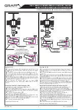
Put the handle assembly
(10B)
onto the spline
(A)
, then holding
acuerdo con la dis. 3.3.
the handle base
(10.1)
, screw the handle assembly onto the thread of
Inserte el juego de la manilla
(10B)
sobre la polichaveta del cabezal
the cartridge until the resistance is felt (fig. 3.4).
(A)
, y luego sujetando la base de la manilla
(10.1)
enrosque el juego de la
To eliminate the distance
(H)
turn the valve
(15B)
manilla sobre la rosca del cabezal hasta sentir la resistencia (dis. 3.4).
counterclockwise until the handle base
(10.1)
reaches the deck
Para eliminar la distancia
(H)
gire la válvula
(15B)
hacia la
(fig.3.5).
izquierda hasta el momento en el que la base de la manilla
(10.1)
se
apoye en la superficie del lavabo (dis.3.5).
Adjustment of position of handle assembly (10B)
Regulación de la ubicación del juego de la manilla (10B)
1. Adjustment of position of handle base
(10.1)
fig. 3.6:
1. Regulación de la ubicación de la base de la manilla
(10.1)
dis. 3.6:
Loosen up the flanged nut
(13)
.
Afloje (desenrosque ligeramente) la tuerca con brida
(13)
.
From underneath the sink turn the valve extension
(10)
in such
Por debajo del lavabo gire la extensión de la válvula
(10)
para
way that, the longer edge of the base
(10.1)
lies in parallel to the deck
lograr que el borde mas largo de la base de la manilla
(10.1)
esté
edge as on fig. 3.6.
paralela al borde del lavabo de acuerdo con la dis. 3.6.
Tighten back the flanged nut
(13)
.
Ajuste la tuerca con brida
(13)
hasta sentir resistencia.
2. Adjustment of handle position
(10.2)
fig. 3.7:
2. Regulación de la ubicación de la manilla
(10.2)
dis. 3.7:
Turn the handle
(10.2)
fully clockwise to the OFF position „valve
Gire la manilla
(10.2)
al máximo hacia la derecha (de acuerdo con
closed” (RIGHT handle - max. counterclockwise direction).
el movimiento de las manillas del reloj) hasta llegar a la posición OFF „la
Turn the valve
(15B)
clockwise until the edge of the handle
válvula cerrada” (la manilla DERECHA - al m
á
ximo hacia la izquierda).
(10.2)
lies in parallel to the handle base edge
(10.1)
.
Gire la válvula
(15B)
hacia la derecha hasta el momento en el cual
Tighten back the flanged nut
(13)
.
el borde de la manilla
(10.2)
esté paralela al borde de la base de la
manilla
(10.1)
.
Repeat steps for second valve.
Ajuste la tuerca de contra
(13)
hasta sentir resistencia.
Repita los pasos con la segunda válvula.
IOG 2061.00
Rev. 4 October 2009
4
3.6
3.7
Installation Instructions
Instrucciones de Instalación
TWO HANDLE WIDESPREAD LAVATORY FAUCET
GRIFO DE DOS MANILLAS DE EXTENSION
10.1
13
HANDLE BASE EDGE
BORDE DE LA BASE
DE LA MANILLA
HANDLE BASE EDGE
BORDE DE LA BASE
DE LA MANILLA
LAVATORY EDGE
BORDE DEL LAVABO
LAVATORY EDGE
BORDE DEL LAVABO
Then turn handle to OFF position
/max. clockwise direction - LEFT handle,
max. counterclockwise direction - RIGHT handle/
Luego gire la manilla a la posición OFF
/al m
á
ximo hacia la derecha - la manilla IZQUIERDA,
al m
á
ximo hacia la izquierda - la manilla DERECHA/
10.1
10.1
10.1
10.1
C9
LM40


