background image

CUTTING PLOTTER 

SERVICE MANUAL 

FC8600-60/75/100/130/160

FC8600-UM-251-07-9370

Summary of Contents for FC8600-100

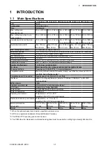
Page 1: ...CUTTING PLOTTER SERVICE MANUAL FC8600 60 75 100 130 160 FC8600 UM 251 07 9370 ...

Page 2: ......

Page 3: ...f Drive Pulley Assy was corrected 9 10 03 10 14 8 27 Parts number of Center Covers were corrected 9 1 04 11 14 8 27 QuantityofPushRollerPositioningLabelSfortheFC8600 60andFC8600 75werecorrected 9 14 04 12 14 8 27 The rank of labels were changed to C rank except I F labels 9 14 04 13 14 11 18 Parts number for LED Base was added 9 4 05 14 14 11 18 The construction of Pen Block Assembly was corrected...

Page 4: ...FC8600 UM 251 9370 II ...

Page 5: ...Gluing Points 5 1 6 DISASSEMBLY AND REASSEMBLY 6 1 6 1 Exterior Parts 6 1 6 1 1 How to Replace the Right Side Cover 6 1 6 1 2 How to Replace the Left Side Cover 6 2 6 1 3 How to Replace the Control Panel Assembly 6 3 6 1 4 How to Replace the Center Cover 6 4 6 1 5 How to Replace the Front Guide 6 5 6 1 6 How to Replace the Rear Guide 6 6 6 1 7 How to Replace the Rear Writing Panel 6 7 6 1 8 How to...

Page 6: ...djustment 7 1 7 2 Mechanical Adjustments 7 2 7 2 1 Y Belt Tension Adjustment 7 2 7 2 2 Y Drive Belt Tension Adjustment 7 3 7 2 3 X Drive Belt Tension Adjustment 7 4 7 2 4 Pinch Roller Pressure Adjustment 7 5 7 3 Electrical Adjustments 7 13 7 3 1 DIP Switch Settings 7 13 7 3 2 Explanation of the Values of the Main Board Settings 7 15 7 3 3 Clearing the Non Volatile RAM 7 16 7 3 4 How to Enter the A...

Page 7: ...es in GP GL Command Mode 8 6 8 4 3 Error Messages in HP GL Emulation Mode 8 7 8 4 4 Error Messages on ARMS 8 9 8 4 5 Other Error Messages 8 12 8 4 6 Warning Messages 8 13 8 5 Service mode 8 14 8 5 1 Sensor Test Mode Panel Switch Test Mode 8 14 8 5 2 Printing the Setting of the Plotter 16 8 5 3 Printing the Test Pattern 17 8 5 4 Confirm the Cutting Data 18 8 5 5 Self Diagnostic Test 19 9 PARTS LIST...

Page 8: ...2 10 2 2 Main Board CONNECTOR 10 3 10 2 3 Main Board MOTOR DRIVER 10 4 10 2 4 Main Board FPGA 10 5 10 2 5 Main Board I F 10 6 10 2 6 Main Board MEMORY 10 7 10 2 7 Main Board Power 10 8 10 2 8 LAN Board 10 9 10 2 9 Light Pointer 10 10 10 2 10 Pen Relay Board 10 11 10 2 11 Pinch Roller Sensor Board 10 12 10 2 12 RMS Board 10 12 10 2 13 Control Panel Board 10 13 10 2 14 Cam Sensor Board 10 14 ...

Page 9: ...ng media shrinkage Number of cutters pens 1 2 for 2 pen model option Pen types Water based fiber tip oil based ballpoint and disposable ink pens Pouncing tool type Pouncing tool PPA33 TP12 1 2 mm pin diameter 3 Compatible media Mono vinyl chloride media fluorescent media and reflective media up to 0 25 mm thick high reflective media 4 Compatible paper for pouncing Regular paper from 0 06 to 0 13 m...

Page 10: ...FC8600 UM 251 9370 1 2 1 INTRODUCTION 1 2 External Dimensions FC8600 60 1128 FC8600 75 1278 FC8600 100 1578 FC8600 130 1878 FC8600 160 2138 715 1219 1162 Units mm Dimensional accuracy 5 mm ...

Page 11: ... the media The rear sensor is used to sense the trailing edge of the media Tool carriage Moves the cutter pen or plotting pen across the media during cutting or plotting Tool holder Holds the cutter pen or plotting pen and moves it up or down Pen station installed on 2 pen models only The second pen is mounted here Factory installed option Stand Used to make the plotter more portable and to free u...

Page 12: ...edium AC line inlet Inlet where the power cord is connected Media stocker Used to carry roll media and ensure its proper rotation Stock rollers A media roll is placed on these rollers Media lock Used to prevent the stock rollers from rotating when the media roll has been placed on top of them The media lock ensures that the media is pulled straight out from the roll USB interface connector Used to...

Page 13: ...s from the plotter control panel depending on the attachment direction Default factory setup is set as rear loading It is recommended to use as rear loading If you desire to load the material from the front it is also possible to use the front loading Use the plotter with enough space behind in this case Also be aware that continuous cutting with cross cut is not possible Assembling the Stand The ...

Page 14: ...nter bar to the left and right stand sides with four socket head cap screws two on each side using the Allen wrench Center bar Stand sides Socket head cap screw Socket head cap screw 3 Attach a media stocker to each of the left and right stand sides with two socket head cap screws using the Allen wrench Mount the media stockers so that each one protrudes directly above the longer of the two base a...

Page 15: ...llen wrench The cutting plotter mounting direction is different for the front loading and the rear loading models Socket head cap screw Positioning pin hole Caster stoppers Socket head cap screw Positioning pin Front loading Rear loading 5 Tighten the socket head cap screws loosely fastened in Step 2 Mounting the stock rollers Insert the stock rollers into the slots on the media stocker brackets F...

Page 16: ...et cap head screws x 4 use Allen wrench to assemble the basket Be sure to use the basket when cutting long axis media of more than 1 meter is to be produced Cloth basket Basket tube long x 3 Socket head cap screw M5 x 4 Mount x 2 Basket tube short x 4 Joint x 4 Assembly 1 Insert the basket tubes long into both ends and center of the basket Attach the joints to the end of the 2 outside basket tubes...

Page 17: ...ed on the basket tubes long at the end of the basket attached in step 1 Mounting position of the center basket pipe long depends on the loading direction Basket tube long Cloth basket Joint For front loading For rear loading 4 Fix the part assembled in 3 to the stand using the socket head cap screws Assembly is completed by separating basket to front and back of the center bar Socket head cap scre...

Page 18: ... is turned on or whenever the tool is moving It is explained here using cutter pen as anexample 1 Loosen the pen holder screw 2 While pushing the tool holder in the upward direction push the tool all the way into the holder until its flange contacts the upper part of the holder When pushing the tool holder with your fingers the blade tip may be protruding Take care not to cut your fingers For half...

Page 19: ...le pushing the pen holder in the upward direction push the pen all the way into the holder until its flange contacts the upper part of the holder When you push the pen holder with your fingers the blade tip may be protruding Take care not to cut your fingers Flange Upper part of pen holder 3 Make sure that the pen bracket is engaged on the pen s flange and then tighten the screw Bracket to hold pe...

Page 20: ...n 2 Make sure that the bracket of the pen station is engaged in the upper groove of the pen 3 Close the pen hold mechanism on the pen station to hold the pen in place Do not leave a pen attached to the pen station for a long period of time as the pen tip will dry up and make it unusable To store the pen remove it from the pen station and replace its protective cap ...

Page 21: ...down 2 Remove the screw holding the cross cutter unit in place and then remove the cross cutter unit Cross cutter unit 3 Remove the protective cover from the replacement cross cutter unit Be sure to remove the protective cover while holding the part of the unit shown in the figure below Protective cover 4 Attach the replacement cross cutter unit and tighten the screw to hold it in place Cross cutt...

Page 22: ...ished cutting STOP Cutting operation will stop immediately when the STOP key is pressed while cutting You can reset the media by pressing the STOP key while cutting when the media has shifted ORIGIN It will set the current position as an origin point The plotter is reset by pressing the ENTER key and the ORIGIN key simultaneously in the first screen of the MENU mode MENU screen Menu Keys MENU It w...

Page 23: ...PERATIONS Indicator Lamps MENU lamp Green lamp is lit while in MENU mode USER 1 2 lamp The lamp for selected user will lit The lamp is lit when the user priority is set to Key Controller It will flash when it is set to Key only ...

Page 24: ...y Manual priority program priority Sort Display when sort is on Prefeed Display when automatic media feed is on Media set lever raised Media set lever lowered Display of Default Screen Valid button is displayed in reverse Screen to set the corresponding conditions is displayed when the MENU key or CONDITION key are pressed MENU CONDITION MENU screen CONDITION screen It will return to default scree...

Page 25: ...s by the ARMS 3 AREA Make the settings for area magnification rotation reverse etc of the cutting 4 MEDIA Make the setting of the condition for the media p I F Make the settings of the condition for the interfacing with the control computer q ADV Make the settings of the conditions for the basic operation of the plotter such as display language unit of the measurements sensor etc t TEST Does the o...

Page 26: ...5 3 OPERATIONS Menu tree Default Screen CONDITION Setting Screen 1 3 CONDITION Setting Screen 2 3 CONDITION Setting Screen 3 3 MENU Screen TOOLS SETTING Screen 1 3 TOOLS SETTING Screen 2 3 Continued TOOLS SETTING Screen 3 3 ...

Page 27: ... 9370 3 6 3 OPERATIONS Continued Default Screen Continued TOOLS SETTING Screen 2 3 MENU Screen TOOLS SETTING Screen 3 3 ARMS SETTING Screen 1 4 ARMS SETTING Screen 2 4 ARMS SETTING Screen 3 4 ARMS SETTING Screen 4 4 ...

Page 28: ...en Continued AREA PARAMETERS Screen 2 2 MEDIA SETTING Screen 1 3 MEDIA SETTING Screen 2 3 INTERFACE Setting Screen 1 3 INTERFACE Setting Screen 2 3 INTERFACE Setting Screen 3 3 Continued MEDIA SETTING Screen 3 3 AREA PARAMETERS Screen 1 2 MENU Screen ...

Page 29: ...FC8600 UM 251 9370 3 8 3 OPERATIONS Default Screen Continued MENU Screen ADVANCE Setting Screen 1 3 ADVANCE Setting Screen 2 3 ADVANCE Setting Screen 3 3 TEST Screen End ...

Page 30: ... Cable FFC707107 1 1 1 1 1 ControlPanelFlexibleCable16Pin 15 792800708 Pen Block Assembly Pen Carriage 1 1 1 1 1 16 792800709 Light Pointer Assembly 1 1 1 1 1 17 682140170 Fan KLDC12B4 940 1 1 2 2 2 18 682140133 LCD JMS12864 15ABAYD 1 1 1 1 1 19 792800711 Cross Cutter Assy 1 1 1 1 1 20 621409600 Y Belt 60 150S2M1000 1 621419600 Y Belt 75 150S2M 1150 1 621429600 Y Belt 100 200S2M 1450 1 621439600 Y...

Page 31: ... or Glue Point Grease or Glue name Application quantity 1 Cam Shinetu silicon grease G501 Suitable quantity 2 X drive motor pulley Shinetu silicon grease G501 Suitable quantity 3 Y drive motor pulley Shinetu silicon grease G501 Suitable quantity 4 X drive pulley Shinetu silicon grease G501 Suitable quantity 5 Y drive pulley Shinetu silicon grease G501 Suitable quantity 6 Y tension pulley Shinetu s...

Page 32: ......

Page 33: ... Replace the Right Side Cover How to detach the right side cover 1 Remove the four M4L6 binding head screws from the right side cover 2 Detach the right side cover M4L6 binding head screw Left side cover How to reinstall the right side cover 1 Reattach the right cover in the reverse order in which it was detached ...

Page 34: ... Cover How to detach the left side cover 1 Remove the four M4L6 binding head screws from the left side cover 2 Detach the left side cover M4L6 binding head screw Right side cover How to reinstall the left side cover 1 Reattach the left cover in the reverse order in which it was detached ...

Page 35: ... 1 2 Remove the three M3L6 binding head screws holding the control panel assembly from the top of the center cover M3L6 binding head screw Control panel assembly 3 Disconnect the two flexible cables from the control panel board Control panel board Flexible cable How to reinstall the control panel assembly 1 Reattach the control panel assembly in the reverse order in which it was detached ...

Page 36: ...ht side cover see Subsection 6 1 1 2 Detach the control panel assembly see Subsection 6 1 3 3 Remove the six M3L6 binding head screws holdong the center cover M3L6 binding head screw Center cover 4 Detach the center cover How to reinstall the center cover assembly 1 Reattach the center cover in the reverse order in which it was detached ...

Page 37: ...move the five M3L6 binding head screws from the front guide for the FC8600 100 Remove the six M3L6 binding head screws from the front guide for the FC8600 130 Remove the seven M3L6 binding head screws from the front guide for the FC8600 160 2 Detach the front guide Front guide M3L6 binding head screw How to reinstall the front guide 1 Reattach the front guide in the reverse order in which it was d...

Page 38: ...Remove the five M3L6 binding head screws from the rear guide for the FC8600 100 Remove the six M3L6 binding head screws from the rear guide for the FC8600 130 Remove the seven M3L6 binding head screws from the rear guide for the FC8600 160 2 Detach the rear guide Rear guide M3L6 binding head screw How to reinstall the rear guide 1 Reattach the rear guide in the reverse order in which it was detach...

Page 39: ...for the FC8600 60 75 Remove the five M3L6 binding head screws from the rear of the rear writing panel for the FC8600 100 Remove the six M3L6 binding head screws from the rear of the rear writing panel for the FC8600 130 Remove the seven M3L6 binding head screws from the rear of the rear writing panel for the FC7000 160 4 Detach the rear writing panel Rear writing panel M3L6 binding head screw M3L6...

Page 40: ...M3L6 binding head screws from the front writing panel assembly for the FC8600 160 4 Loosen the five M3L6 binding head screws at the top of the front writing panel assembly for the FC8600 60 75 Loosen the six M3L6 binding head screws at the top of the front writing panel assembly for the FC8600 100 Loosen the seven M3L6 binding head screws at the top of the front writing panel assembly for the FC86...

Page 41: ...rear media sensor 1 Detach the rear guide see Subsection 6 1 6 2 Remove the M3L10 binding head screw attaching the rear media sensor 3 Disconnect the sensor from the connector Rear media sensor M3L10 binding head screw How to reinstall the rear media sensor 1 Reattach the rear media sensor in the reverse order in which it was detached ...

Page 42: ... the M3L6 binding head screw attaching the front media sensor bracket Front media sensor bracket M3L6 binding head screw Front media sensor 3 Remove the M3L10 binding head screw attaching the front media sensor M3L10 binding head screw 4 Disconnect the sensor from the connector How to reinstall the front media sensor 1 Reattach the front media sensor in the reverse order in which it was detached ...

Page 43: ...ler 1 Detach the right side of the E ring from the pinch roller shaft E ring Pinch roller shaft Pinch roller 2 Detach the pinch roller shaft from the pinch roller arm from the left side 3 Detach the pinch roller How to reinstall the pinch roller 1 Reattach the pinch roller in the reverse order in which it was detached ...

Page 44: ...er assembly Release the hooks holding the control panel board and then detach the control panel board from the control panel cover Control panel cover Control panel board 3 Remove the four nylon rivets holding the LCD from the control panel board Control panel board LCD Nylon rivet 4 Detach the LCD from the control panel board How to reinstall the control panel board and the LCD 1 Reattach the con...

Page 45: ...ver see Subsection 6 1 4 3 Loosen the two M3L6 binding head screws attaching the pen block cover M3L6 binding head screw 4 Detach the pen block cover 5 Disconnect the cables from connector J502 J504 J505 and J506 on the Y relay board Disconnect these cables from the connectors Y relay board 6 Remove the two M4L6 binding head screws attaching the pen block M4L6 binding head screw Pen block ...

Page 46: ... the bottom of the pen block and the cutting mat Perform a visual check to make sure that the pen block is not mounted at an angle 10 mm 3 Reattach the other parts in the reverse order in which they were detached 4 Perform the pen force adjustment see Section 7 3 5 5 Perform the auto registration mark sensor sensitivity adjustment see Section 7 3 7 6 Perform the auto registration mark sensor offse...

Page 47: ...Subsection 6 1 2 2 Detach the center cover see Subsection 6 1 4 3 Detach the pen block see Subsection 6 2 5 4 Loosen the two M3L35 binding head screws adjusting the Y belt tension M3L35 binding head screw 5 Remove the four M3L6 binding head screws attaching the right and left Y belt stopper plates to the slider Y belt M3L6 binding head screw 6 Detach the Y belt from the unit ...

Page 48: ...des of the pulley 3 Attach both ends of the Y belt to the Y slider so that four notches of the Y belt fit into the Y slider then attach with the Y belt stopper plates removed in step 5 in the previous subsection M3L6 binding head screw Y belt Four notches of the Y belt fit into the Y slider 4 Attach the pen block see Subsection 6 2 5 5 Reattach the other parts in the reverse order in which they we...

Page 49: ... 5 Remove the M3L6 binding head screw attaching the pinch roller sensor bracket to the slider Y slider M3L6 binding head screw Pinch roller sensor bracket Pinch roller sensor board 6 Remove the two M3L6 binding head screws attaching the pinch roller sensor guard Pinch roller sensor guard M3L6 binding head screw Pinch roller sensor bracket Pinch roller sensor board 7 Remove the M3L6 binding head sc...

Page 50: ...ller sensor board 3 Attach the pinch roller sensor guard to the pinch roller sensor board bracket 4 Attach the pinch roller bracket to the Y slider Fit the top and left edges of the pinch roller bracket to the Y slider as shown in the figure below M3L6 binding head screw Pinch roller sensor bracket 5 Attach the pen block see Subsection 6 2 5 6 Reattach the other parts in the reverse order in which...

Page 51: ...ts attaching the flexible cable holding plate Plastic rivet Flexible cable holding plate 3 Disconnect all the cables from the Y relay board 4 Remove the two M3L6 binding head screws attaching the Y relay board Y relay board M3L6 binding head screw 5 Detach the Y relay board from the Y slider How to reinstall the Y relay board 1 Reattach the Y relay board in the reverse order in which it was detach...

Page 52: ...e cam sensor 1 Detach the right side cover see Subsection 6 1 1 2 Disconnect the cable from the cam sensor M3L6 binding head screw Cam sensor 3 Remove the M3L6 binding head screw attaching the cam sensor How to reinstall the cam sensor 1 Reattach the cam sensor in the reverse order in which it was detached ...

Page 53: ...the Y motor pulley then detach the Y motor How to reinstall the Y motor 1 Attach the Y motor to the Y motor bracket 2 Hang the Y drive belt on the Y motor pulley and the Y idler pulley 3 Attach the Y motor pulley to the Y motor 4 Tighten the two M3L4WP set screws that hold the Y motor pulley 5 Spread a suitable quantity of Loctite 222 on the two M3L4WP set screws that hold the Y motor pulley 6 Spr...

Page 54: ...stall the X motor 1 Attach the X motor to the right side plate 2 Hang the X drive belt on the X drive pulley 3 Attach the X motor pulley to the X motor 4 Tighten the two M3L4WP set screws that hold the X motor pulley 5 Spread a suitable quantity of Loctite 222 on the two M3L4WP set screws that hold the X motor pulley 6 Perform the X drive belt tension adjustment see Subsection 7 2 3 7 Tighten the ...

Page 55: ...onnect all the cables and flexible cables from their connectors on the main board 3 Remove the four M3L6 binding head screws holding the main board to the chassis 4 Detach the main board from the chassis M3L6 binding head screw Main board How to reinstall the main board 1 Reattach in the reverse order in which it was detached 2 Perform any adjustments required see Section 7 1 ...

Page 56: ...see Subsection 6 1 5 2 Disconnect the vacuum fan from the relay connector Relay connector Vacuum fan 3 Use a long screwdriver to remove the two M3L35 binding head screws holding the vacuum fan as shown in the figure below Vacuum fan 4 Detach the vacuum fan How to reinstall the vacuum fan 1 Reattach in the reverse order in which it was detached ...

Page 57: ...n the X drive belt 5 Remove the two M3L4WP set screws holding the X drive pulley and detach the X drive pulley from the drive roller M3L6 binding head screw M3L4WP set screw X motor drive pulley X motor X drive belt 6 Remove the X drive belt from the X motor pulley 7 Remove the M3L6 binding head screws holding the bearing covers and detach the bearing covers from the pillow blocks Don t remove the...

Page 58: ...ity of Loctite 222 on the two M3L4WP set screws holding the X drive pulley 3 Perform the X drive belt tension adjustment see Subsection 7 2 3 4 Spread a suitable quantity of the Shinetu silicon grease G501 on the X motor pulley 5 Move the X drive pulley and check the tension of the X drive belt 6 Reattach the other parts in the reverse order in which they were detached ...

Page 59: ... mat 1 Peel off the cutting mat from the cutting mat base How to reinstall the cutting mat 1 Clean the surface of the cutting mat base with alcohol where the cutting mat was attached 2 Attach the new cutting mat to the cutting mat base 3 Make sure that there is no air between the cutting mat and the cutting mat base ...

Page 60: ... you remove or replace the dog as shown below If you have an error about the pinch roller position confirm position of this dog 115 mm Home position dog 6 2 17 Cross Cutter Dog Position Cross cutter dog position Adjust the cross cutter position dog when you remove or replace the dog as shown below 91 mm Cross cutter position dog ...

Page 61: ... X Y Motor drive belt Auto registration mark sensor NOV RAM clear M Pen force adjustment M M Distance adjustment M M M Auto registration mark sensor adjustment N N N M Light pointer adjustment N M N Firmware upgrade M Belt tension adjustment M M M Pinch roller pressure adjustment M 2 Pen option adjustment N N DIP switch setting N Servo gain adjustment N N No mark Unnecessary M Must always be adjus...

Page 62: ... the way to the right and pull the belt 20 mm towards the center using a force gauge Adjust the Y tension pulley adjustment screws evenly until the tension reads as follows Specification of the Belt Tension Model Force gauge reading specification FC8600 60 700 g 50 FC8600 75 700 g 50 FC8600 100 700 g 50 FC8600 130 700 g 50 FC8600 160 700 g 50 20 mm 700 g 50g Y idler pulley Y belt 4 Verify that the...

Page 63: ...our M3L6 binding head screws that hold the Y motor 3 Use the force gauge to pull the Y drive motor pulley flange with a 2 25 kg force 4 Tighten the four M3L6 binding head screws that hold the Y motor 5 Spread a suitable quantity of the Shinetu silicon grease G501 on the Y motor pulley 6 Move the pen block and check the tension of the Y drive belt 7 Reattach the right side cover ...

Page 64: ... screws that hold the X motor 3 Use the force gauge to push the X drive motor pulley flange with a 800 g force as shown in the figure below M3L6 binding head screw 4 Tighten the mounting screws that hold the X motor 5 Spread a suitable quantity of the Shinetu silicon grease G501 on the X motor pulley 6 Move the X drive pulley and check the tension of the X drive belt 7 Reattach the right side cove...

Page 65: ... position 3 Hang the wire as shown in the picture below and then measure the force by using the push pull gauge Hang the wire to the push roller shaft 4 The push roller force should be 6 5 kg 0 25 kg 5 Adjust the push roller force at locatin shown in the picture below Adjusting position for each push rollers FC8600 60 FC8600 75 FC8600 100 FC8600 130 FC8600 160 Middle push rollers Right push roller...

Page 66: ...er 3 Set the push roller force lever to the lower position for the high force 4 Loosen the screw upper screw holding the force adjustment bracket as shown in the picture below Loosen this screw 5 Measure the push roller force and then adjust the push roller force by using the force adjustment screw as shown in the picture below The push roller force should be 6 5 kg 0 25 kg The difference between ...

Page 67: ...g the force adjustment bracket as shown in the picture below Tighten this screw 8 Set the push roller force lever to the lower position for the high force 9 Loosen the screw Lower screw holding the bracket as shown in the picture below Loosen this screw 10 Confirm there is no gap between the top of tension lever and the bottom of tension bracket Confirm there is no gap here ...

Page 68: ...FC8600 UM 251 9370 7 8 7 ADJUSTMENT 11 Tighten the screw Lower screw holding the bracket as shown in the picture below Tighten this screw ...

Page 69: ...3 Set the push roller force lever to the lower position for the high force 4 Loosen the screw upper screw holding the force adjustment bracket as shown in the picture below Loosen this screw 5 Measure the push roller force and then adjust the push roller force by using the force adjustment screw as shown in the picture below The push roller force should be 6 5 kg 0 25 kg Push roller force adjustme...

Page 70: ...screw holding the force adjustment bracket as shown in the picture below Tighten this screw 8 Set the push roller force lever to the upper position for the low force 9 Loosen the screw Lower screw holding the bracket as shown in the picture below Loosen this screw ...

Page 71: ...p part of the bracket will be bent if you tighten this screw strongly Lower position adjustment screw 11 Confirm there is no gap between the top of tension and the bottom of tension bracket Confirm here there is no gap between the top of tension and the bottom of tension bracket 12 Spread the screw lock glue 1401B to the lower position adjustment screw after the lower position was adjusted Lower p...

Page 72: ...FC8600 UM 251 9370 7 12 7 ADJUSTMENT 13 Tighten the screw Lower screw holding the bracket as shown in the picture below Tighten this screw ...

Page 73: ...l SW1 1 2 3 4 5 6 7 8 ON OFF SW1 1 2 3 4 5 6 7 8 ON OFF FC8600 75 FC8600 75 2 Pen Model SW1 1 2 3 4 5 6 7 8 ON OFF SW1 1 2 3 4 5 6 7 8 ON OFF FC8600 100 FC8600 100 2 Pen Model SW1 1 2 3 4 5 6 7 8 ON OFF SW1 1 2 3 4 5 6 7 8 ON OFF FC8600 130 FC8600 130 2 Pen Model SW1 1 2 3 4 5 6 7 8 ON OFF SW1 1 2 3 4 5 6 7 8 ON OFF FC8600 160 FC8600 160 2 Pen Model SW1 1 2 3 4 5 6 7 8 ON OFF SW1 1 2 3 4 5 6 7 8 O...

Page 74: ... 7 14 7 ADJUSTMENT NOV RAM Clear FC8600 60 SW1 1 2 3 4 5 6 7 8 ON OFF FC8600 75 SW1 1 2 3 4 5 6 7 8 ON OFF FC8600 100 SW1 1 2 3 4 5 6 7 8 ON OFF FC8600 130 SW1 1 2 3 4 5 6 7 8 ON OFF FC8600 160 SW1 1 2 3 4 5 6 7 8 ON OFF ...

Page 75: ...ample record are shown below 25 47 100 228 346 X 0 X 80 X Y 4 Y 50 Y Explanation of the values Pen force values 10 g 40 g 120 g 300 g 450 g 400 g Distance adjustment values Gain adjustment values Auto registration mark position adjustment values X X X Y Y Y You can input the same values when you have replaced the main board without making any adjustments If you have changed any values by making ad...

Page 76: ...le RAM 1 Set SW1 to the NOV RAM clear mode as shown below FC8600 60 SW1 1 2 3 4 5 6 7 8 ON OFF FC8600 75 SW1 1 2 3 4 5 6 7 8 ON OFF FC8600 100 SW1 1 2 3 4 5 6 7 8 ON OFF FC8600 130 SW1 1 2 3 4 5 6 7 8 ON OFF FC8600 160 SW1 1 2 3 4 5 6 7 8 ON OFF 2 Turn on the power to the plotter 3 The NOVRAM CLEAR START menu appears The plotter immediately starts to clear the parameters on the NOV RAM and then se...

Page 77: ...4 5 6 7 8 ON OFF FC8600 75 FC8600 75 2 Pen Model SW1 1 2 3 4 5 6 7 8 ON OFF SW1 1 2 3 4 5 6 7 8 ON OFF FC8600 100 FC8600 100 2 Pen Model SW1 1 2 3 4 5 6 7 8 ON OFF SW1 1 2 3 4 5 6 7 8 ON OFF FC8600 130 FC8600 130 2 Pen Model SW1 1 2 3 4 5 6 7 8 ON OFF SW1 1 2 3 4 5 6 7 8 ON OFF FC8600 160 FC8600 160 2 Pen Model SW1 1 2 3 4 5 6 7 8 ON OFF SW1 1 2 3 4 5 6 7 8 ON OFF ...

Page 78: ...nd ENTER keys Or After turning on the power press the FAST key and the ENTER key simultaneously within 2 seconds 2 Load a sheet of paper in the plotter 3 The plotter displays the menu shown below 4 Press the MENU key to display the menu shown below 5 Press the Right Position key to display the adjustment menu shown below ...

Page 79: ...mark sensor level adjustment Registration mark sensor position adjustment Cross cutter position adjustment 2 pen height position adjustment Not used Cross cutter height position adjustment Not used Light pointer position adjustment 2 pen type confirmation Registration sensor level adjustment Debug menu Not used Not used Not used Not used Not used Not used Not used Not used Not used Not used Not us...

Page 80: ...key to display the menu shown below Don t select AUTO 6 The pen is lowered If you have replaced the moving coil and or the pen block assembly use the force gauge to measure the actual force If you have only replaced the main board input the adjustment values that were recorded Use the UP ARROW key or DOWN ARROW key to change the force setting The number on the LCD will increase or decrease If you ...

Page 81: ... to store the setting The next specified pen force appears 10 Adjust the 400 g pen force If the measured value is within the specification range or if you have input the recorded value press the ENTER key to store the setting Note When adjusting the pen force it is important to do it quickly Delaying the pen force adjustment changes the temperature of the actuator and causes artificially lower rea...

Page 82: ... distance accuracy 1 Enter the adjustment menu see Section 7 3 4 2 Load an A2 or larger size sheet of paper in the plotter 3 Mount a fiber tip pen in the pen holder 4 Press the UP arrow or Down arrow key until the menu shown below is displayed 5 Press the F1 key to display the menu shown below 6 Press the F2 key to select the fiber tip pen the menu shown below 7 Press the ENTER key to set the fibe...

Page 83: ... shown below if you want to adjust the X axis distance and then input the value for the X axis distance Press the F3 key to display the menu shown below if you want to adjust the Y axis distance and then input the value for the Y axis distance To Input the values using the POSITION keys The UP and DOWN ARROW keys are used to change the Y axis or X axis adjustment value If you input the measured va...

Page 84: ... diagonal distance XY which was measured 14 Press the left arrow key to display the menu shown below Adjusted value will be displayed 15 Press the ENTER key to store the setting 16 Press the down arrow key to draw the adjusted pattern and then confirm the distance adjustment that the adjusted pattern has 300 mm x 300 mm 17 If you wish to complete this adjustment press the left arrow key 18 Turn of...

Page 85: ...e used 3 Press the UP arrow or Down arrow key until the menu shown below is displayed 4 Press the F4 key to display the menu shown below 5 Press the F2 key to draw the cross pattern 6 Use the ARROW keys to move the pen to an open area to adjust the registration mark sensor gain 7 Press the ENTER key to start the registration mark sensor gain adjustment The plotter immediately adjusts the registrat...

Page 86: ...f paper in the plotter The paper color must be white and it is recommended that high quality paper made for ink jet printers be used 3 Mount a fiber tip pen in the pen holder 4 Press the UP arrow or Down arrow key until the menu shown below is displayed 5 Press the F1 key to display the menu shown below 6 Press the F2 key to select the fiber tip pen 7 Press the ENTER key to set the fiber tip pen 8...

Page 87: ...attern 13 Press the ENTER key to plot the adjustment pattern shown below Plotted target mark Adjustment lines 14 The plotter immediately adjusts the registration mark sensor position automatically and adds a vertical line and a horizontal line to the scanned plotted pattern 15 Measure the offset between the lines and confirm that they are within 0 25 mm 16 Press the ENTER key to store the setting ...

Page 88: ...er in the plotter The paper must cover the front and rear media sensors 3 Lower the media set lever to raise the pinch rollers and then raise the media set lever to detect the paper size The menu shown below is displayed after the media set lever is raised 4 Press the down arrow key until the menu shown below is displayed 5 Press the F2 key to display the menu shown below 6 Press the F1 key to dis...

Page 89: ...elease plate 0 to 0 2 mm 9 Press the left arrow key to display the menu shown below 10 Press the F4 key to confirm the gap If the cross cutter dog presses on the cutter release plate too much a position alarm error will be displayed At this time reduce the C CUTTER POS ADJ value 11 Press the ENTER key to store the setting 12 Turn off the power to exit from the adjustment menu ...

Page 90: ...4 2 Load an A2 or larger size sheet of paper in the plotter 3 Mount a fiber tip pen in the pen holder 4 Press the UP arrow or Down arrow key until the menu shown below is displayed 5 Press the F1 key to display the menu shown below 6 Press the F2 key to select the fiber tip pen the menu shown below 7 Press the ENTER key to set the fiber tip pen 8 Press the UP arrow or Down arrow key until the menu...

Page 91: ...ea to plot the adjustment pattern 11 Press the ENTER key to plot the adjustment pattern shown below 12 Move the light pointer to the center of the adjustment pattern using the POSITION keys 13 Press the ENTER key to register the position 14 Turn off the power to exit from the adjustment menu ...

Page 92: ...ure to make the 2 pen model setting 1 Load an A2 or larger size sheet of paper in the plotter 2 Enter the adjustment menu see Section 7 3 4 3 Press the Up or Down position key until the menu shown below is displayed 4 Press the F2 key to display the menu shown below 5 Press the F3 key to select the DIPSW 6 Press the ENTER key to set the DIPSW 7 Turn off the power to exit from the adjustment menu ...

Page 93: ...s OFF if the 2 pen system FC8600 60 2 Pen Model SW1 1 2 3 4 5 6 7 8 ON OFF FC8600 75 2 Pen Model SW1 1 2 3 4 5 6 7 8 ON OFF FC8600 100 2 Pen Model SW1 1 2 3 4 5 6 7 8 ON OFF FC8600 130 2 Pen Model SW1 1 2 3 4 5 6 7 8 ON OFF FC8600 160 2 Pen Model SW1 1 2 3 4 5 6 7 8 ON OFF ...

Page 94: ...m that the DIP switch 7 of SW1 is OFF 2 pen model mode 2 Enter the adjustment menu see Section 7 3 4 3 Press the Up or the Down position key until the menu shown below is displayed 4 Press the F3 key to display the menu shown below 5 Press the F2 key to move the pen carriage to the exchange position This gap should be 1 1 mm 6 Press the F3 key to display the following menu to adjust the gap 7 Adju...

Page 95: ... to 1 1 mm This gap should be 1 1 mm 10 Mount a fiber tip pen in the 2nd pen station 11 Press the F4 key to confirm that the pen exchanging is performed correctly 12 If the pen exchanging is performed correctly press the ENTER key to store the setting and complete the adjustment ...

Page 96: ...re 1 Enter the adjustment menu see Section 7 3 4 2 Load an A2 or larger size sheet of paper in the plotter 3 Mount the fiber tip pens in the 1 pen holder and 2 pen station 4 Press the UP arrow or Down arrow key until the menu shown below is displayed 5 Press the F1 key to display the menu shown below 6 Press the F2 key to select the fiber tip pen the menu shown below 7 Press the ENTER key to set t...

Page 97: ...he ENTER key to display the menu shown below 13 Press the F2 key to display the menu shown below 14 Use the ARROW keys to move the pen to an open area to plot the adjustment pattern 15 Press the ENTER key to plot the cross marks by pen 1 and pen 2 shown below Media feed direction Lines plotted by pen 2 Cross mark plotted by pen 1 Y X Y Y X X ...

Page 98: ...below 19 Set the X offset value Press the UP ARROW key or DOWN ARROW key to change the number based on the pen 1 cross mark 20 Press the left position key when the X direction is adjusted 21 Press the F4 key to display the menu shown below 22 Set the Y offset value Press the UP ARROW key or DOWN ARROW key to change the number based on the pen 1 cross mark 23 Press the left position key when the Y ...

Page 99: ...4 Press the F2 key Verify that the plotted pen 1 cross mark is located at the center of the plotted pen 2 lines 25 If the plotted cross marks are in the correct positions press the ENTER key to store the setting and complete the adjustment ...

Page 100: ...mm position from the right side panel as shown in the following picture 80 5mm Right side plate Pen Block Cover 2 Turn on the power while holding down both the TEST and ENTER keys 3 Press the MENU key to display the adjustment menu and then press the POSITION key to display the following menu 4 Press the POSITION key until the following menu is displayed 5 Set the ball point pen to the tool 2 pen ...

Page 101: ...he ENTER key 11 Press the 4 key to select C CUTTER THRESHOLD Input the value of TOOL 2 value 5 which was displayed at the Tool 2 adjustment Press the 2 key Press the POSITION key to increase or decrease the value to set For Example Input the 170 175 5 to the Cross Cutter threshold if the Tool 2 reading height value is 175 12 Confirm the setting and press the POSITION key PREVIOUS 13 When the corre...

Page 102: ... ARROW and RIGHT ARROW keys Or After turning on the power press the LEFT ARROW key and the RIGHT ARROW key simultaneously within 2 seconds 4 The plotter displays the menu shown below UPDATE No 5 Select Yes using the UP ARROW or DOWN ARROW key UPDATE Yes 6 Press the ENTER key to display the menu shown below PLEASE SEND PRG 7 Send firmware to the plotter from the computer Execute SEND EXE Select the...

Page 103: ...FC8600 UM 251 9370 7 43 7 ADJUSTMENT ...

Page 104: ...e front media sensor dirty Yes Clean the front media sensor No Verify item 3 3 Is the front media sensor cable securely connected to the main board and the sensor Yes Replace the front media sensor No Connect the cable securely The media drops to the rear of the plotter 1 Is the rear edge of the media curled Yes Replace the media No Verify item 2 2 Is the rear media sensor dirty Yes Clean the rear...

Page 105: ...r No Attach the drive roller correctly 8 3 Cutting Operations Symptom Verification item Solution The cut line is crooked 1 Does the blade turn well in the blade holder No Replace the blade holder Yes Verify item 2 2 Do the X and Y drive motor belts have the correct tension No Adjust the tension No Verify item 3 3 Is the Y belt attached correctly No Attach it correctly Yes Verify item 4 4 Is the pe...

Page 106: ...HOOTING 8 4 Error Messages 8 4 1 Hardware Error Messages Error code Error Display Cause Verification item Solution E01001 to E01005 Main board is defective Replace the main board E01006 E01007 E01008 E01009 E01010 E01011 E01012 E01013 ...

Page 107: ...and or the cutting FORCE Movement of the X is being obstructed Is there anything blocking the X movement Turn off the plotter remove the obstacle then turn the plotter back on Excessive load is causing the current to the motor to exceed the rated value Does the X move smoothly No Check and adjust the X belt tension and X motor belt tension Yes Verify item 2 Is the X flexible cable securely connect...

Page 108: ... tension Yes Verify item 2 2 Is the Y flexible cable securely connected Or Is the Y flexible cable broken No Connect it securely Yes Replace the Y flexible cable if defective Home sensor or sensor plate adjustment 1 Is the Y home sensor plate position correct No Check and adjust the X home sensor position Yes Replace the X home sensor if defective 2 Is the Y home sensor position correct No Check a...

Page 109: ...ion 3 Has the correct model name been set for the plotter No Set the correct model name Configure your software application menu to permit Graphtec plotter control Re specify the software application s interface conditions E02004 The software configuration regarding the output device has been changed The plotter s interface conditions have been changed The numeric parameter of an input command exc...

Page 110: ...d the plotter receive an unrecognizable command No Verify item 2 Yes Send correct data to plotter 2 Is there any noise on the line No Verify item 3 Yes Check the interface cable or move the plotter to another location 3 Has the correct model name been set for the plotter No Set the correct model name Configure your software application menu to permit Graphtec plotter control Re specify the softwar...

Page 111: ...10 Other output command was executed while executing an output command Check the program E03011 An invalid byte was received after ESC code E03012 Invalid byte was received within device control command E03013 A parameter outside of the permissible range was specified in the I O related command E03014 Too many parameters in the I O related command E03015 Framing error parity error or overrun error...

Page 112: ...gistration scan position E04006 Amount of data has exceeded the I O buffer size for the segment area registration mark Decrease the data E04007 Test pattern plotting position is not within the plotting area for sensor position adjustment Move the media toward center and plot the test pattern E04008 Media end was detected while detecting the registration mark Check the media Check the print positio...

Page 113: ...owered Reload the media and try again E04019 There was cancel operation by the user Redo the process E04021 Registration mark was not detected in the auto detection area Check the media Check the print position of the registration mark E04022 There was cancel operation by the user Redo the process E04023 Registration mark was not detected Redo the sensor level adjustment Change the color of the re...

Page 114: ...OOTING Error code Error Display Cause Solution E04024 Registration mark was not detected Redo the sensor level adjustment Change the color of the registration mark Check the media Check the print position of the registration mark E04025 ...

Page 115: ...4 The push roller is not on the grit roller Check the push roller position Set the push roller on the grit roller E05005 It has failed to cross cut The media was not cut off Check the blade for the cross cut Check the media on the writing panel Replace the cross cutter blade if the cross cutter blade is defective E05006 Distance between the bottom left and top right of the AREA setting is less tha...

Page 116: ... is disabled Enable the push roller sensor W06005 Cross cut function cannot be used when the media sensor is disabled Enable the media sensor W06007 CONDITION No that has selected pouncing tool as the tool number setting can only set TOOL 1 Select TOOL 1 W06008 When command is set to auto the DUMP mode is not available Select the command setting to the HP GL or the GP GL W06009 When panel cutting ...

Page 117: ...shown below Short form Sensor or key Short form Sensor or key Short form Sensor or key Short form Sensor or key UP Up arrow key DN Down arrow key LT Left arrow key RT Right arrow key YHME Y home sensor PROL Pinch roller sensor CAM Cam sensor XFRONT Front media sensor XREAR Rear media sensor STOP STOP key MENU Menu key COPY Copy key CCUT Cross Cut key FAST Fast key ORIG Origin key COND Condition ke...

Page 118: ...FC8600 UM 251 9370 8 15 8 TROUBLESHOOTING 11 When testing is completed turn off the power to the plotter ...

Page 119: ...ion where the pen tool is set 3 Press the MENU key to display the menu below 4 Press the POSITION t key TEST to display the menu below 5 Press the 1 key CONDITION LIST to display the menu below 6 Press the 1 key DONE 1 2 or the 2 key DONE 2 2 Message to confirm tool position is displayed 7 Move the tool carriage to print start position by using the POSITION key 8 Press the ENTER key to start print...

Page 120: ...ze 2 Set the pen tool to the tool carriage and select the condition where the pen tool is set 3 Press the MENU key to display the menu below 4 Press the POSITION t key TEST to display the menu below 5 Press the 2 key SELF TEST to display the menu below 6 Confirm that the pen tool is set 7 Press the 1 key DONE to print the test pattern 8 Turn the power off to stop the printing ...

Page 121: ...and select the condition where the pen tool is set 3 Press the MENU key to display the menu below 4 Press the POSITION t key TEST to display the menu below 5 Press the 3 key DATA DUMP to display the menu below 6 Confi rm that the pen tool is set 7 Confi rm that operation area of tool and media is safe 8 Press the 1 key DONE 9 Output the data to plotter from the PC The dump list starts when the plo...

Page 122: ...6 Press the 1 key DONE The first testing menu is displayed And follow the instructions on the menu 7 Press the 1 key to continue to the next test after you check the CAM lever sensor 8 The testing items are shown below 1 Cam lever sensor 2 Home sensor 3 Push roller sensor 4 Rear media sensor 5 Font media sensor 6 X motor signal 7 Y motor signal 8 Tool height signal 9 1 key 10 2 key 11 3 key 12 4 k...

Page 123: ... Writing Panel 100 1 FC8600 100 C 621430101 Front Writing Panel 130 1 FC8600 130 C 621440101 Front Writing Panel 160 1 FC8600 160 C 7 621390042 Rear Writing Panel 60 1 FC8600 60 C 621261045 Rear Writing Panel 75 1 FC8600 75 C 621271045 Rear Writing Panel 100 1 FC8600 100 C 621281045 Rear Writing Panel 130 1 FC8600 130 C 621291046 Rear Writing Panel 160 1 FC8600 160 C 8 792800720 Main Board for FC8...

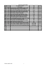
Page 124: ...FC8600 UM 251 9370 9 2 9 PARTS LIST Outer Casing 4 6 2 3 9 13 11 12 14 15 10 1 16 8 7 5 ...

Page 125: ... 3 621632020 Key Top Cursor 86 1 C 4 621632050 Key Top Function 86 1 C 5 621632030 Key Top Right 86 1 C 6 621632040 Key Top Left 86 2 C 7 792800790 Control Panel Board 86 1 A 8 682140133 LCD JMS12864 15ABAYD 1 A 9 692140322 Flexible Cable FPC707102 1 20P J801 to J3 B 10 692140372 Flexible Cable FPC707107 1 16P J802 to J22 LCD Cont B Control Panel 1 4 6 6 5 7 9 10 8 3 2 ...

Page 126: ...20 Bearing Roller 2 683ZZMC3PS2S D 13 621403010 Moving Coil Base 1 Replace by the pen block assembly D 14 500050122 Encoder Sensor HEDS 9720 P50 1 Replace by the pen block assembly D 15 Registration Mark Sensor Assy 1 See Registration Mark Sensor Assy Part 16 792800711 Cross Cutter Assy 1 B 17 621113520 Rubber plate 1 Replace by the pen block assembly D 18 622192091 Arm Spring 2 1 For 2 pen model ...

Page 127: ...FC8600 UM 251 9370 9 5 9 PARTS LIST Pen Block Pen Holder for 2 pen Model 21 Pen Station for 2 pen Model 23 5 3 6 4 8 7 15 16 11 27 17 12 9 10 28 13 14 2 1 22 18 19 20 20 25 19 23 26 21 22 24 ...

Page 128: ...ank 1 621403200 Spring Cover Down 1 C 2 621263340 Spring RMS Up 1 C 3 500052472 Core Solenoide 1 B 4 Solenoide 1 5 621263312 Bracket RMS sensor 1 C 6 792800704 Registration Mark Sensor Board 1 A 7 621263331 Paper Hold Down B 1 C 8 621263322 Paper Hold Down A 1 C Registration Mark Sensor Assy 1 3 2 6 4 7 8 5 ...

Page 129: ...63453 Shaft Cross Cutter 1 D 3 621263460 Latch TL 294 1 B 4 621403120 Arm Catch 1 D 5 621403100 Cross Cutter Base 1 D 6 380265331 Spring E 533 1 D 7 621353010 Thumb Screw L10 1 B 8 CT01H Cross Cutter Blade Standard Type 1 Consumption goods D CT02U Cross Cutter Blade High durability Type 1 Consumption goods D Cross Cutter 1 4 2 7 5 8 6 3 ...

Page 130: ...A 11 682132431 Motor UGJMEE A7JGR34 1 X Motor FC8600 100 130 160 A 682126201 Motor DMN37HE 003 1 X Motor FC8600 60 75 A 12 561080004 Media Sensor PS 117ED1 2 A 13 621260011 Pillow Block 5 FC8600 60 FC8600 75 D 621260011 Pillow Block 7 FC8600 100 D 621260011 Pillow Block 9 FC8600 130 D 621260011 Pillow Block 11 FC8600 160 D 14 621260132 Media Sensor Bracket 1 D 15 310014820 Roller B MR148ZZMC3PS2S ...

Page 131: ...FC8600 UM 251 9370 9 9 9 PARTS LIST Main Frame 1 3 4 5 7 8 9 10 11 12 6 2 15 16 13 14 20 21 22 17 18 19 ...

Page 132: ...ler Arm Shaft 1 4 FC8600 60 75 C 6 FC8600 100 130 8 FC8600 160 19 621230111 Cam 2 FC8600 60 75 C 4 FC8600 100 130 3 FC8600 160 20 621401301 Pinch Roller Base 2 FC8600 60 75 B 3 FC8600 100 130 4 FC8600 160 21 621263052 Stopper Plate R 2 D 22 621401311 Lever Spring 2 FC8600 60 75 C 3 FC8600 100 130 4 FC8600 160 23 621401690 Spring Pinch Roller 2 FC8600 60 75 D 3 FC8600 100 130 4 FC8600 160 24 621401...

Page 133: ...2140361 Y Flexible Cable FPC707106 1 FC8600 160 A 35 621271250 Flexible Cable Reinforcement Strip Plate 100 1 FC8600 100 C 621281250 Flexible Cable Reinforcement Strip Plate 130 1 FC8600 130 C 621291250 Flexible Cable Reinforcement Strip Plate 160 1 FC8600 160 C 36 792800702 Pen Relay Board 1 A 37 621403090 Pen Carriage Cover 1 C Y Rail 1 3 4 5 13 6 9 10 12 7 11 11 8 14 28 29 30 31 32 33 37 34 35 ...

Page 134: ... Sensor Board 1 A 3 621173150 Pinch Roller Sensor Bracket B 1 C 4 095013010 Slider Roller BB13 8 C 5 621403300 Y Slider 1 C 6 621183410 Roller Tension Plate L 1 C 7 392330200 Spacer C320 2 For FC8600 130 160 only C 8 792800702 Pen Relay Board 1 C 9 621183420 Y Belt Fixing Plate L 51 2 C 10 395130020 Spacer CB302E 2 C Y Slider 1 2 3 4 4 9 5 4 4 6 6 10 7 8 4 ...

Page 135: ... Main Board 1 FC8600 160 C 4 692140120 Cable CA707112 Main Board to Cam Sensor 1 C 5 692140311 Flexible Cable FFC707101 Pinch Roller Sensor 1 C 6 692140322 FlexibleCable FFC707102 MainBoardJ3toControlPanelBoardJ1 1 B 7 692140372 FlexibleCable FFC707107 MainBoardJ22toControlPanelBoard 1 B 8 692140181 Cable CA707118A X Motor Extension Cable 1 FC8600 100 130 160 C 9 692140240 Cable CA707124 X Motor C...

Page 136: ...8600 60 C 621634260 Model Label FC8600 75 1 FC8600 75 C 621634360 Model Label FC8600 100 1 FC8600 100 C 621634460 Model Label FC8600 130 1 FC8600 130 C 621634560 Model Label FC8600 160 1 FC8600 160 C 6 621264390 Standby Label 1 C 7 621264330 I F Label 1 D 621404410 I F Label w LAN port 1 D 8 621264410 Push Roller Positioning Label S 6 FC8600 60 C 8 FC8600 75 C 12 FC8600 100 C 16 FC8600 130 C 20 FC...

Page 137: ...00 100 C 621430140 Center Bar 130 1 FC8600 130 C 621440290 Center Bar 160 1 FC8600 160 C 4 621400150 Stock Roller 60 2 FC8600 60 C 621410150 Stock Roller 75 2 FC8600 75 C 621420150 Stock Roller 100 2 FC8600 100 C 621430150 Stock Roller 130 2 FC8600 130 C 621440260 Stock Roller 160 2 FC8600 160 C 5 621400902 Side Stay Assembly 2 C 6 621400930 Foot Base Assembly 2 C 7 Hexagonal Wrench M5 1 D 8 Socke...

Page 138: ...21639950 FC8600 DVDM01M 1 FC8600 C 3 621639960 Quick Manual 86 1 FC8600 C Regarding the rank of spare parts Rank A This rank of part will be stocked always until product discontinued Rank B This rank of part will not be stocked always This rank of parts will need a lead time maximum 3 months Rank C This rank of part will not be stocked always This parts will need a lead time at least 3 month Rank ...

Page 139: ... 4 5 6 2 1 FILM SENSOR REAR CA707101 60 75 CA707102 100 CA707103 130 CA707104 160 CA707106 CA707107 CA707110 100 CA707111 130 CAMZ GND 5V 3 2 1 B3B PH J5 CA707112 FFC707107 CA707113 FH12 22S 1 0SH J501 FFC707101 FFC707103 60 75 FFC707104 100 FFC707105 130 FFC707106 160 CA707116 FFC707102 CA707115 CN2 PN7071 05 GND GND 1 2 3 4 5 6 7 8 9 10 LCD_RESETPZ LCD_LCD_CS1Z LCD_RD WR LCD_WE0Z LCD_D 7 LCD_D 6...

Page 140: ...FC8600 UM 251 9370 10 2 10 BLOCK DIAGRAMS AND CIRCUIT DIAGRAMS 10 2 Circuit Diagrams 10 2 1 Main Board CPU Use for the debug monitor This connector is not mounted ...

Page 141: ...FC8600 UM 251 9370 10 3 10 BLOCK DIAGRAMS AND CIRCUIT DIAGRAMS 10 2 2 Main Board CONNECTOR ...

Page 142: ...FC8600 UM 251 9370 10 4 10 BLOCK DIAGRAMS AND CIRCUIT DIAGRAMS 10 2 3 Main Board MOTOR DRIVER ...

Page 143: ...FC8600 UM 251 9370 10 5 10 BLOCK DIAGRAMS AND CIRCUIT DIAGRAMS 10 2 4 Main Board FPGA ...

Page 144: ...FC8600 UM 251 9370 10 6 10 BLOCK DIAGRAMS AND CIRCUIT DIAGRAMS 10 2 5 Main Board I F ...

Page 145: ...FC8600 UM 251 9370 10 7 10 BLOCK DIAGRAMS AND CIRCUIT DIAGRAMS 10 2 6 Main Board MEMORY ...

Page 146: ...FC8600 UM 251 9370 10 8 10 BLOCK DIAGRAMS AND CIRCUIT DIAGRAMS 10 2 7 Main Board Power When the LAN is connected ...

Page 147: ...FC8600 UM 251 9370 10 9 10 BLOCK DIAGRAMS AND CIRCUIT DIAGRAMS 10 2 8 LAN Board ...

Page 148: ...FC8600 UM 251 9370 10 10 10 BLOCK DIAGRAMS AND CIRCUIT DIAGRAMS 10 2 9 Light Pointer ...

Page 149: ...FC8600 UM 251 9370 10 11 10 BLOCK DIAGRAMS AND CIRCUIT DIAGRAMS 10 2 10Pen Relay Board ...

Page 150: ...FC8600 UM 251 9370 10 12 10 BLOCK DIAGRAMS AND CIRCUIT DIAGRAMS 10 2 11 Pinch Roller Sensor Board 10 2 12RMS Board RMS SENSOR BOARD ...

Page 151: ...FC8600 UM 251 9370 10 13 10 BLOCK DIAGRAMS AND CIRCUIT DIAGRAMS 10 2 13Control Panel Board ...

Page 152: ...FC8600 UM 251 9370 10 14 10 BLOCK DIAGRAMS AND CIRCUIT DIAGRAMS 10 2 14Cam Sensor Board ...

Reviews: