background image

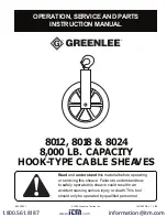
OPERATION, SERVICE AND PARTS

INSTRUCTION MANUAL

©1996 Greenlee Textron Inc.

IM 1260 REV 1   4/96

8012, 8018 & 8024

8,000 LB. CAPACITY

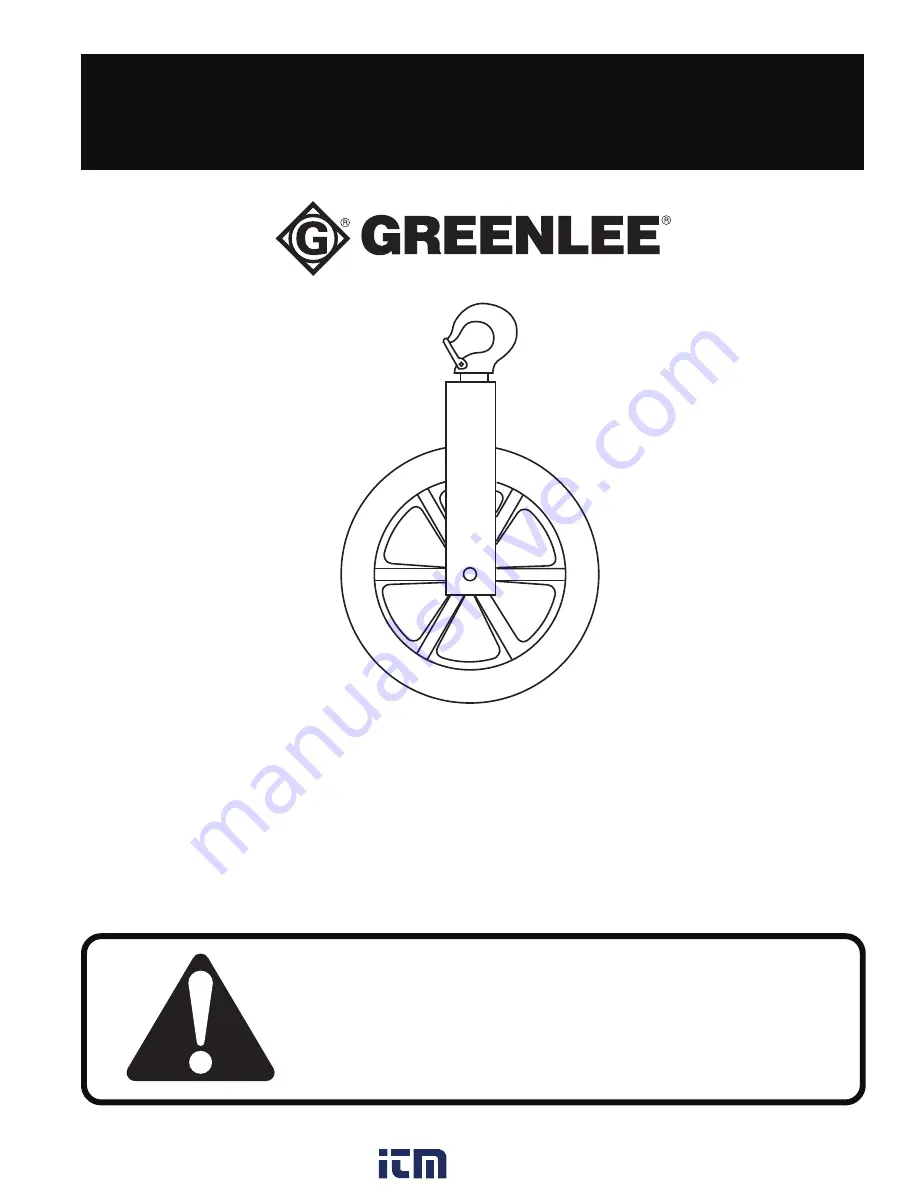
HOOK-TYPE CABLE SHEAVES

999 2092.1

Read

 and 

understand

 this material before operating

or servicing this sheave. Failure to understand how
to safely operate this sheave could result in an
accident causing serious injury or death. This tool
should only be operated by qualified personnel.

www.

.com

information@itm.com

1.800.561.8187

Summary of Contents for 783310008729

Page 1: ...OOK TYPE CABLE SHEAVES 999 2092 1 Read and understand this material before operating or servicing this sheave Failure to understand how to safely operate this sheave could result in an accident causin...

Page 2: ...ttention to instructions concerning your personal safety Watch for this symbol It points out important safety pre cautions It means ATTENTION Become alert Your personal safety is involved Read the mes...

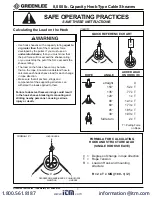
Page 3: ...ual to or greater than that of the maximum force developed by the puller If you must use an under rated sheave then you must know that the pull force will not exceed the sheave rating or you must stop...

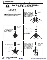
Page 4: ...ds nearly one and a half times pulling force to the load on the hook and structure A straight rope will not add any load to the hook and structure A rope making a 150 bend over the sheave adds half th...

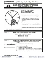
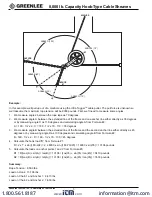
Page 5: ...A and B Figure 2 by measuring angles C and D and using Formula 2 below Calculate the loads R1 and R2 using Formula 3 below FORMULA FOR CALCULATING ANGLES A AND B Measure angles C and D see Figure 2 AN...

Page 6: ...3 We measure angle B between the extended line of the frame and the second anchor line either directly as 45 degrees or by measuring angle D as 100 degrees and calculating angle B from Formula 2 B 180...

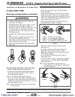
Page 7: ...g hook S 320 S 322 S 319 Important Safety Information Read and Follow Always visually inspect hook before using Inspect hook and threads with magnetic particle and or dye penetrate annually or more of...

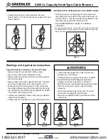
Page 8: ...the load See Figure 3 The latch must never support the load See Figure 4 When placing two 2 sling legs in hook make sure the angle from the vertical to the outermost leg is not greater than 45 and the...

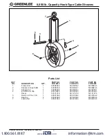
Page 9: ...heave Unit with 6 1 500 0843 9 500 0844 7 500 0845 5 3 Sheave Pin 1 500 0838 2 500 0846 3 500 0850 1 4 8 Hitch Pin Clip 1 905 0302 3 905 0302 3 905 0302 3 Decal 1 501 2121 9 501 2121 9 501 2121 9 5 Ro...

Reviews: