background image

1

OPERATOR’S MANUAL


www.grip-rite.com

 AND PARTS LIST

GRTFR83, GRTFR83L, GRTFC83 & GRTFW83 

SHORT BODY FRAMING NAILERS

MODELS

GRTFW83

GRTFC83

GRTFC83

GRTFW83

GRTFR83(L)

GRTFR83(L)

All manuals and user guides at all-guides.com

all-guides.com

Summary of Contents for GRTFC83

Page 1: ...www grip rite com AND PARTS LIST GRTFR83 GRTFR83L GRTFC83 GRTFW83 SHORT BODY FRAMING NAILERS MODELS GRTFW83 GRTFC83 GRTFC83 GRTFW83 GRTFR83 L GRTFR83 L All manuals and user guides at all guides com a l l g u i d e s c o m ...

Page 2: ... yourself with all safety operating and service instructions before loading handling or using your tool When used correctly pneumatic fastening tools provide a lightweight powerful and safe means of fastening Used improperly these tools can cause serious injury to you and those around you GRTFC83 Fastener Selection Chart GRTFW83 Fastener Selection Chart GRTFR83 L GRTFC83 GRTFW83 GRTFR83 PARTS SCHE...

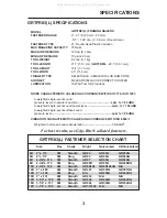
Page 3: ...d single event sound power level LwA 1s 102 dBA A weighted single event surface sound pressure level LpA 1s 89 dBA VIBRATION CHARACTERISTIC VALUES IN ACCORDANCE WITH ISO 8862 1 2 Weighted root mean square acceleration 3 6 m s For best results use Grip Rite collated fasteners GRTFR83 L FASTENER SELECTION CHART 6D 2 x 113 5M Smooth GR03 GR05G GR05HG 6D 2 x 113 5M Ring GR04 GR04G GR04HG 8D 2 3 8 x 11...

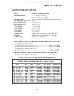
Page 4: ...A weighted single event surface sound pressure level LpA 1s 89 dBA VIBRATION CHARACTERISTIC VALUES IN ACCORDANCE WITH ISO 8862 1 2 Weighted root mean square acceleration 3 6 m s For best results use Grip Rite collated fasteners GRTFC83 FASTENER SELECTION CHART 6D 2 x 113 2 5M Smooth GRSP6D GRSP6DG GRSP6DHG 6D 2 x 113 2 5M Ring GRSP6DR GRSP6DRG GRSP6DRHG 8D 2 3 8 x 113 2 5M Smooth GRSP8D GRSP8DG GR...

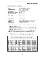
Page 5: ...vent surface sound pressure level LpA 1s 89 dBA VIBRATION CHARACTERISTIC VALUES IN ACCORDANCE WITH ISO 8862 1 2 Weighted root mean square acceleration 3 6 m s For best results use Grip Rite collated fasteners GRTFW83 FASTENER SELECTION CHART 6D 2 x 113 2 5M Smooth GRS6D GRS6DG GRS6DHG 6D 2 x 113 2 5M Ring GRS6DR GRS6DRG GRS6DRHG 8D 2 3 8 x 113 2 5M Smooth GRS8D GRS8DG GRS8DHG 8D 2 3 8 x 113 2 5M R...

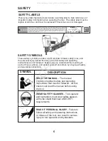
Page 6: ...S Tool operator and bystanders must wear safety glasses with side shield that meet ANSI Z87 1 requirements RISK OF PERSONAL INJURY Failure to follow all safety and operating instructions or misuse of the tool can result in serious injury to tool operator and bystanders WARNING USER MUST READ OPERATION MANUAL BEFORE USING TOOL TO REDUCE THE RISK OF INJURY FAILURE TO FOLLOW THESE OPERATIONS MAY RESU...

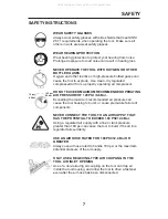
Page 7: ...aximum recommended air pressure can cause the tool housing to burst or cause premature failure of components NEVER CONNECT THE TOOL TO AN AIR SUPPLY THAT HAS THE POTENTIAL TO EXCEED 180 PSI 12 4 Bar Using a regulated air supply with a line or tank pressure greater than 180 psi can cause the tool to burst if the air line regulator fails suddenly USE AN AIR HOSE RATED FOR 180 PSI 12 4 Bar OR GREATER...

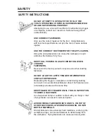
Page 8: ...ver point the tool at yourself or anyone else when loading fasteners DO NOT LOAD TOOL WITH TRIGGER OR WORKPIECE CONTACT DEPRESSED Depressing the trigger or workpiece contact during loading can result in an unintentional fastener drive if both devices are accidentally actuated at the same time KEEP FINGER OFF TRIGGER UNTIL TOOL IS IN POSITION TO DRIVE A FASTENER An unexpected bump or sudden contact...

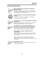
Page 9: ...rge and injury to yourself or others DISCONNECT THE TOOL FROM THE AIR SUPPLY TO RELOAD CLEAR JAMS OR PERFORM MAINTENANCE Never attempt to reload a tool clear a jam or perform maintenance without frst disconnecting the air supply NEVER LEAVE A LOADED PRESSURIZED TOOL UNATTENDED A loaded pressurized tool could be picked up or handled by someone who is unfamiliar with the tool or that has not read th...

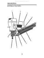
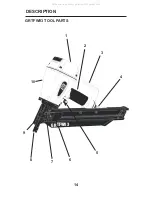
Page 10: ...10 DESCRIPTION GRTFR83 L TOOL PARTS 1 2 3 8 6 7 11 10 9 5 4 All manuals and user guides at all guides com ...

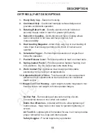
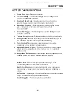
Page 11: ...vides positive fastener feeding in all tool positions Dry fire lockout prevents blank firing 9 Work Contact Tip Agressive claw design permits stable positioning for toe nailing in all applications 10 Adjustable Depth of Drive Tool free depth of drive adjustment allows nail drive adjustments to be made at tool for consistent depth control 11 Magnesium Tool Housing Light weight durable magnesium too...

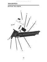
Page 12: ...12 DESCRIPTION GRTFC83 TOOL PARTS 1 2 3 7 5 6 10 9 8 4 GRTFC83 All manuals and user guides at all guides com ...

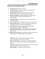
Page 13: ...y fire lockout prevents blank firing 8 Work Contact Tip Agressive claw design permits stable positioning for toe nailing in all applications 9 Adjustable Depth of Drive Tool free depth of drive adjustment allows nail drive adjustments to be made at tool for consistent depth control 10 Magnesium Tool Housing Light weight durable magnesium tool housing lowers tool weight reduces operator fatigue No ...

Page 14: ...14 DESCRIPTION GRTFW83 TOOL PARTS 1 2 3 7 5 6 10 9 8 4 GRTFW83 All manuals and user guides at all guides com ...

Page 15: ...y fire lockout prevents blank firing 8 Work Contact Tip Agressive claw design permits stable positioning for toe nailing in all applications 9 Adjustable Depth of Drive Tool free depth of drive adjustment allows nail drive adjustments to be made at tool for consistent depth control 10 Magnesium Tool Housing Light weight durable magnesium tool housing lowers tool weight reduces operator fatigue No ...

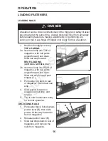
Page 16: ...d forward and down Slide nail strip forward REAR LOADING 2b Insert nail strip into REAR of magazine with nail points angled forward and down Slide nail strip forward past 3 Pull pusher A back to rear of magazine behind last nail strip 4 Slide pusher forward to engage last nail strip and release 5 Tool is now loaded and ready for normal operation UNLOADING NAILS 1 Pull pusher back fully depress pus...

Page 17: ...drive 4 Make depth of drive adjustments as needed to maintain consistent nail driving NAIL TOO HIGH TURN DIAL BACKWARD NAIL TOO DEEP TURN DIAL FORWARD D SELECTING TRIGGER OPERATION 1 Disconnect tool from air supply using quick connect coupling BUMP FIRE OPERATION 2a Slide the selector button E on the trigger to the forward position SEQUENTIAL FIRE OPERATION 2b Slide the selector button E on the tr...

Page 18: ...obtain desired fastener drive 7 If tool adjustments do not provide the desired results make air pressure adjustments at the compressor Increase air pressure to drive deeper or to drive into harder materials Reduce air pressure to reduce drive or to drive into softer materials For longest tool and part life always use the lowest air pressure necessary to drive fasteners to desired depth 8 Position ...

Page 19: ...tool off using a parts cleaning brush or clean rag Check area around trigger and workpiece contact and clean as necessary Trigger Check Check trigger operation daily to confirm proper sequential operation 1 Move the selector button on the trigger to the rear position 2 Press the workpiece contact against a safe work surface without depressing the trigger THE TOOL MUST NOT CYCLE 3 Hold the tool abo...

Page 20: ...GRTFR83 PARTS SCHEMATIC 20 All manuals and user guides at all guides com ...

Page 21: ...RTN2550 Spring Pin 47 GRTN790 Pin Trigger 48 GRTN6960 Guide Safety Lever 49 GRTN2210 Grommet 50 GRTN7000 O Ring 51 GRTN6790 Nose 52 GRTN2010 Hex Soc Hd Bolt 53 GRTN6810 Spring Safety 54A GRTN6800 Upper Safety Lever Assy 55 GRTN2660 E ring 56 GRTN6840 Adjusting Nut 57 GRTN6850 Adjusting Spring 58A GRTN6820 Lower Safety Lever Assembly 59 GRTN1530 Rubber Pad 60 GRTN6600 Door Hinge Pin 61 GRTN6640 Spi...

Page 22: ...22 GRTFR83L PARTS SCHEMATIC All manuals and user guides at all guides com ...

Page 23: ...pring Pin 46 GRTN2550 Spring Pin 47 GRTN790 Pin Trigger 48 GRTN6960 Guide Safety Lever 49 GRTN2210 Grommet 50 GRTN7000 O Ring 51 GRTN6790 Nose 52 GRTN2010 Hex Soc Hd Bolt 53 GRTN6810 Spring Safety 54A GRTN7200 Upper Safety Lever Assy 55 GRTN2660 E ring 56 GRTN6840 Adjusting Nut 57 GRTN6850 Adjusting Spring 58A GRTN6820 Lower Safety Lever Assembly 59 GRTN1530 Rubber Pad 60 GRTN6600 Door Hinge Pin 6...

Page 24: ...24 GRTFC83 PARTS SCHEMATIC All manuals and user guides at all guides com ...

Page 25: ...g Pin 46 GRTN2550 Spring Pin 47 GRTN790 Pin Trigger 48 GRTN6960 Guide Safety Lever 49 GRTN2210 Grommet 50 GRTN7000 O Ring 51 GRTN7500 Nose 52 GRTN2010 Hex Soc Hd Bolt 53 GRTN7510 Spring Safety 54A GRTN7520 Upper Safety Lever Assy 55 GRTN2660 E ring 56 GRTN6840 Adjusting Nut 57 GRTN6850 Adjusting Spring 58A GRTN6820 Lower Safety Lever Assembly 59 GRTN1530 Rubber Pad 60 GRTN6640 Spiral Spring 61 GRT...

Page 26: ...26 GRTFW83 PARTS SCHEMATIC All manuals and user guides at all guides com a l l g u i d e s c o m ...

Page 27: ... Spring Pin 46 GRTN2550 Spring Pin 47 GRTN790 Pin Trigger 48 GRTN6960 Guide Safety Lever 49 GRTN2210 Grommet 50 GRTN7000 O Ring 51 GRTN7670 Nose 52 GRTN2010 Hex Soc Hd Bolt 53 GRTN7680 Spring Safety 54A GRTN7690 55 GRTN2660 E ring 56 GRTN6840 Adjusting Nut 57 GRTN6850 Adjusting Spring 58A GRTN7700 Lower Safety Lever Assembly 59 GRTN1530 Rubber Pad 60 GRTN6640 Spiral Spring 61 GRTN6890 Roller 62 GR...

Page 28: ... Do not exceed 120 psi 8 3 bar Fasteners do not drive completely when driv ing in quick succes sion Inadequate air fow Use larger diameter hose Use compressor with larger storage tank Keep hose lines short Check air hose for kinks or other restrictions Fasteners drive too deeply AT COMPRESSOR Reduce air pressure Do not reduce below 70 psi 4 8 bar PROBLEM CORRECTIVE ACTION Fasteners do not drive co...

Page 29: ...gazine TOOL CHECKS Keep your nailer in top working condition by checking it daily See your Grip Rite dealer for service if part or operating problems are found Never use a malfunctioning tool it could result in serious injury Workpiece Contact Trigger Check workpiece contact for proper operation before each use Workpiece contact must move freely and return to extended position when lifted from wor...

Page 30: ...RIP RITE TOOLS GRIP RITE COMPRESSORS parts have been used The tool has suffered any physical damage due to the use of non PRIMESOURCE approved fasteners Repairs are required due to normal wear tear The tool compressor has been inadequately packaged leading to damage in transit to the service warranty center Approved fasteners include the following brands GRIP RITE FAS NERS FAS NERS UNLIMITED IN NO...

Page 31: ...ly at Phone 800 207 9259 or Fax 800 207 9614 Adequately package the product to avoid damage in transit in the case of pneumatic tools the original blow mold plastic carrying case is considered adequate packaging Provide the original copy of receipt showing the original purchase date Insure your shipment with the shipping company PRIMESOURCE will not be responsible for any tool compressor that is l...

Page 32: ...22 USE GENUINE GRIP RITE FASTENERS FOR BEST PERFORMANCE GRTF83MAN 9 10 www grip rite com All manuals and user guides at all guides com ...

Reviews: