
GRIPPLE INC.
1611 EMILY LANE
AURORA, IL 60502 USA
Phone: 1-630-406-0600
www.grippleseismic.com
DATE:
3/14/2013
PAGE:
1 / 2
GRIPPLE
®
SEISMIC
CABLE BRACING INSTALLATION GUIDE
(READ INSTRUCTIONS IN THEIR ENTIRETY BEFORE STARTING INSTALLATION)
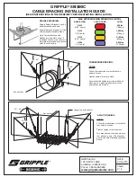
Attachment to structure. Gripple cable end fitting
(Eyelet, Standard bracket, or Double Bracket).
Select bracket based on anchor diameter.
Break strength
certified, pre-stretched
Gripple Seismic Cable
Gripple Seismic
Fastener
(GS10, GS12,
GS19, GS25)
Hanger rod
with stiffener
as required,
or equipment
attachment
Attachment to equipment/strut.
Gripple GSS or GSR Bracket.
Select size based on hanger rod
diameter.
Color coded tag
(see Side 2 for
details)
Brace angle
30º - 60º
IMPORTANT INFORMATION:
a.) Each cable brace should be
at an angle between 30-60
degrees to the horizontal, as
shown in drawing at left; 45
degrees is optimal.
b.) Ensure that suitable rod
stiffener is used to prevent
buckling or bending of the
rod in the event of an
earthquake.
Gripple Seismic Cable End Fittings:
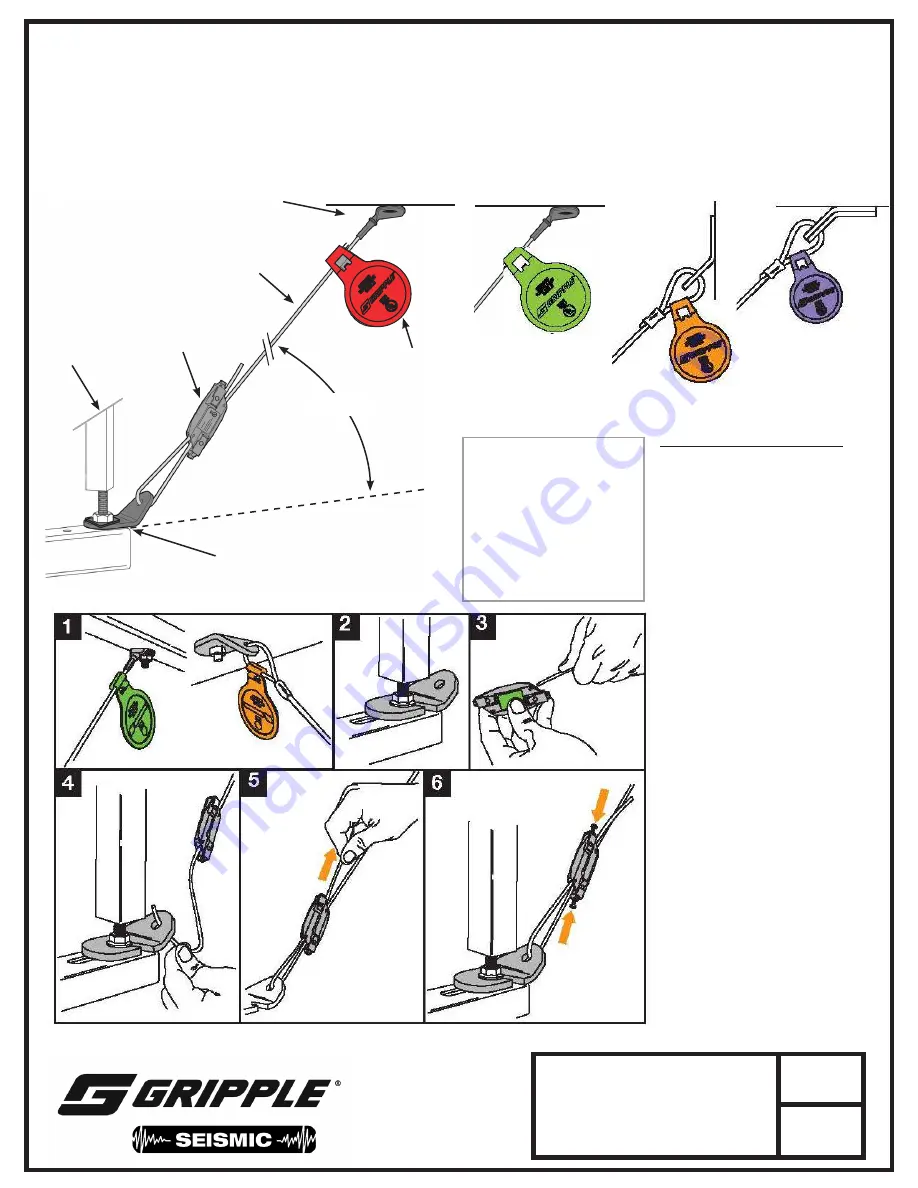
INSTALLATION INSTRUCTIONS:
1.) Install Gripple Seismic end fitting
(Eyelet or Bracket for GS10 or GS12;
Single Bracket for GS19, or Double
Bracket for GS25, as shown above)
to structure.
2.) Loosen the nut on the rod hanger and
slot the Gripple Seismic Retrofit Bracket
onto the rod. Tighten the nut onto the
Gripple Seismic Retrofit Bracket.
Ensure that the appropriate washer
per the cable & bracket system being
used is installed and the nut is
tightened down securely onto the
bracket.
3.) Thread free end of cable through first
channel of the Gripple Seismic fastener.
4.) Thread free end of cable through the
hole in the Gripple Seismic bracket.
5.) Position the Gripple Seismic fastener
up the cable so that it is a min. of 12
inches above the bracket. Thread the
remaining cable through the second
channel in the Gripple Seismic fastener
to form a loop around the bracket.
Pull the tail end of the cable to create
a tight loop, and remove the slack
from the Gripple Seismic cable brace.
Use the Gripple supplied Tightening
Tool for the GS19 and GS25 systems.
6.) Trim the tail end of the cable but leave
a minimum tail length of 2 inches.
Install the locking bolts and ensure
that they are tightened down securely.
Ensure that locking bolts are removed
before trying to remove further slack
from the cable or adjust the position of
the Gripple Seismic fastener along the
cable length.
GS10
(Eyelet or Bracket)
GS12
(Eyelet or Bracket)
GS19
(Single Bracket)
GS25
(Double Bracket)


