


1
GROWSPAN
™
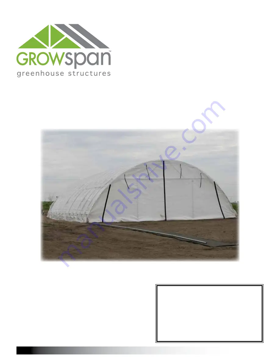
ROLLING PREMIUM HIGH TUNNELS
Revision date: 01.01.16
Photo may show a different but similar model.
STK#
DIMENSIONS
111770
30' W x 12' H x 24' L
111771
30' W x 12' H x 36' L
111772
30' W x 12' H x 48' L
111773
30' W x 12' H x 60' L
111774
30' W x 12' H x 72' L
111775
30' W x 12' H x 84' L
111776
30' W x 12' H x 96' L
GrowSpan
™
Rolling Premium High Tunnels
©2016 GrowSpan
All Rights Reserved. Reproduction
is prohibited without permission.


