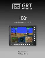
GRT Avionics HXr, Installation Manual
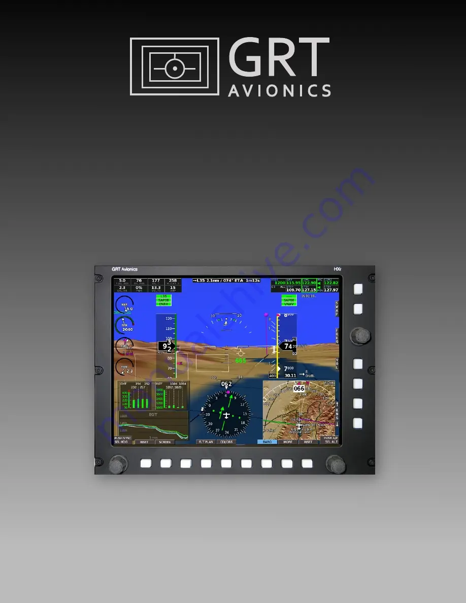
The GRT Avionics HXr is a highly advanced avionics system designed to enhance your aircraft's performance and safety. Our Installation Manual provides detailed step-by-step instructions on how to easily integrate the HXr into your aircraft. Download the free manual from our website for seamless installation and optimal utilization of this exceptional product.
Share
Download
Reviews:
No comments