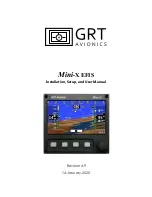
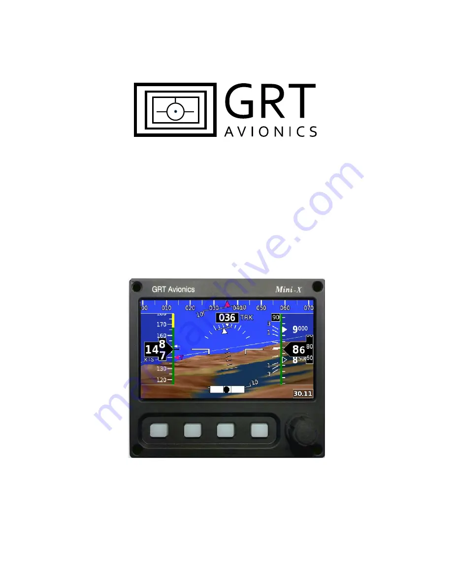
background image

Mini

-X EFIS

Installation, Setup, and User Manual

Revision A9

14-January-2020

Summary of Contents for Mini-X EFIS

Page 1: ...Mini X EFIS Installation Setup and User Manual Revision A9 14 January 2020...

Page 2: ...Mini X Installation Setup User Manual GRT Avionics Revision A9 2 3133 Madison Ave SE Wyoming MI 49548 616 245 7700 www grtavionics com Copyright 2014...

Page 3: ...image of North Up map presentation with compass rose Section 6 4 Added information about the Synthetic Approach Section 7 4 A4 29 Aug 2014 1d Fixed typographical errors in Section 4 6 and 4 7 A5 11 Fe...

Page 4: ...r upgrade must be accompanied by a Service Request Form downloadable from the GRT website Support section Satisfaction Guarantee If for any reason you are unhappy with your GRT product you may return...

Page 5: ...ctor Definition 15 2 2 General Wiring Guidelines 17 2 3 Power Connections 17 2 4 Autopilot Source Switch Optional 18 2 5 Magnetometer Wiring Optional Recommended 18 2 6 Inter Display Communication 19...

Page 6: ...timeter Calibration 32 4 9 Full Altimeter Calibration Using Air Data Test Set 33 4 10 Airspeed and Wind Calibration 35 4 11 Angle of Attack AOA Installation and Calibration 37 5 1 Primary Flight Displ...

Page 7: ...8 7 1 GPS CDI Bar 59 7 2 Flight Planning with the Mini 59 7 3 Airport Facilities Information Radio Tuning 65 7 4 Synthetic Approach SAP 66 8 1 Autopilot 68 8 2 Trig TT22 Transponder 69 8 3 Graphical E...

Page 8: ...ferences for Installation In addition to basic mechanical hand tools a D sub pin crimper is required in most installations A basic 4 way indent crimper is available from SteinAir for less than 35 We s...

Page 9: ...of the remote unit 1 4 1 Mini X AHRS and Loss of GPS Data Normal Operation Attitude data will be full accuracy when valid external magnetometer data or GPS ground track data is available If no valid e...

Page 10: ...RT Avionics Revision A9 10 Figure 1 1 Mini Dimensional Drawing all models GRT Mini 01 Mar 2014 Notes Cutout dimensions 4 15 x 3 30 Unit is centered within the cutout Mounting screws are 4 Mounting bol...

Page 11: ...are displayed between button presses refer to Section 4 3 General Preferences for more information 1 5 1 Overview of Pages Softkeys The Mini X has a Primary Flight Display page a Flight Plan entry pag...

Page 12: ...igation Source Synthetic Vision Display Options Settings Main Menu Turn to adjust Altimeter Setting Press for Autopilot PFD Level 3 Softkeys typical Error or Warning Details Manually Record or Play De...

Page 13: ...views HSI Screen Dimmer or Trans ponder Turn to adjust map range Press once for Heading Bug Press again for Map Selection Tool cursor and Nearest selection softkeys Map Level 2 Softkeys typical Choos...

Page 14: ...ug Press again for Map Selection Tool cursor and Nearest selection softkeys Error or Warning Details More items Turn to adjust map range Press once for Heading Bug Press again for Map Selection Tool c...

Page 15: ...titude calculations when the Mini does not have a serial connection to a working GRT Horizon or Sport EFIS display unit Use Trig TT22 A and B connections for control and encoder information for the TT...

Page 16: ...Mini X Installation Setup User Manual GRT Avionics Revision A9 16 GPS Antenna Mini USB Port DB15 Connector male Pitot Port Static Port Figure 2 1 Rear Case View Connector Placement...

Page 17: ...ns typically found in aircraft Some consideration should be given to avoid routing wires near antennas or other locations that could impart high levels of electromagnetic signals on the wiring The che...

Page 18: ...om the Support Documentation Autopilot section of our website for more information on wiring and setup of the GRT autopilot Note In autopilot wiring setup documentation the Mini is treated the same as...

Page 19: ...ltimeter setting and screen dimming can be made from any display unit and will be applied to all Designate one serial port pair for the Mini and another for the GRT display you want to connect it to a...

Page 20: ...sponder directly to ground to allow the transponder to power up Option 2 Wire the Trig to both the Mini and one other GRT EFIS screen Applicable only to Sport SX and Horizon HX HXr Because Sport and H...

Page 21: ...he same For example the Mini can take GPS position from a handheld GPS but it can t talk back to the GPS therefore the GPS only requires the IN half of the serial port The Mini transmits encoder data...

Page 22: ...Connections The pitot static connections on the back of the Mini are labeled P pitot and S static and take a 1 8 27 NPT male fitting To facilitate installation and removal of the Mini unit quick disco...

Page 23: ...on its side for easier mounting The side of a wing tip rib is a simple place to put it The arrow on the magnetometer should be parallel with the centerline of the airplane for yaw Pitch attitude is no...

Page 24: ...for the Mini are found on the Set Menu pages To access 1 Press any key to display the softkey labels then press NEXT until a SET MENU softkey appears 2 Press SET MENU to access the main menu as displ...

Page 25: ...may choose to display the Map or HSI If you have two Minis installed one can be set to the PFD while the other can default to the Map page Speed Distance Units Choose your preferred units for the airs...

Page 26: ...of the magnetometer if installed 1 Access Set Menu AHRS Maintenance Scroll to Set Instrument Orientation 2 Enter the offset in degrees for each axis Positive corrections correspond to right roll pitch...

Page 27: ...f information The Magnetic Heading field contains instantaneous data on magnetic heading only 4 Observe the Magnetic Heading and verify it does not change by more than 2 degrees while doing the follow...

Page 28: ...he magnetic heading should be approximately correct if this step was correctly performed and the magnetometer is not located near excessive magnetic inteference 4 7 Fine Magnetometer Calibration Proce...

Page 29: ...out 30 degrees of 360 4 Access Set Menu AHRS Maintenance Scroll to and select Magnetometer Calibration field on this screen 5 Press Start soft key The first question is Are you sure Press YES if you a...

Page 30: ...be reduced to about 2 degrees Accurate magnetic heading is required for the AHRS to display accurate heading data and to allow accurate wind speed direction calculations The graph will also show the c...

Page 31: ...etometer be installed in a good location on the airplane and the AHRS be mounted accurately Due to the steep angle of the earth s magnetic fields only about 20 degrees off vertical the attitude data f...

Page 32: ...ta test set and may be performed on an annual basis or as needed as follows 1 Position the aircraft at a location with a known elevation 2 Turn on the Mini and allow at least 5 minutes to elapse befor...

Page 33: ...ads 0 feet 8 Set the altimeter test set to 30 000 ft and note the Mini altimeter reading 9 Calculate the scale factor as follows Calculate the Altitude Error as Altitude_Error GRT Sport_Altimeter_Read...

Page 34: ...10000 15000 etc and adjusting the corresponding entry until the altimeter reads this altitude 13 The accuracy of the scale factor adjustment can be verified by noting a small altitude error less than...

Page 35: ...mprovement in the accuracy of the winds can be achieved by performing this calibration The Mini does not provide any means to correct the indicated airspeed as this would result in the Mini showing a...

Page 36: ...ain constant heading and altitude until the count down timer reaches 0 The Mini will average the data until the timer reaches 0 8 Turn to the reciprocal heading when prompted When established on this...

Page 37: ...ic block on the rear of the instrument Calculated AOA Installation No installation is required as the angle of attack is computed from the AHRS pitch attitude true airspeed and vertical speed Note tha...

Page 38: ...Mini X Installation Setup User Manual GRT Avionics Revision A9 38 airplane near stall speed When performing this step minimal power should be used and the flaps should be in the retracted position...

Page 39: ...because the Mini s location on the instrument panel will usually have too much electromagnetic interference for precise measurement of heading The Mini X and Mini AP come standard with synthetic visi...

Page 40: ...points to the predicted speed of the aircraft in 5 seconds at the current rate of acceleration V Speed Reference Markers The airspeed tape also features three programmable V speed reference markers th...

Page 41: ...rectangle Five hundred foot increments are depicted by a hollow marker The baro setting is displayed in the lower right corner The terrain clearance color band on the edge of the altimeter tape shows...

Page 42: ...esired altitude into the Altitude Preselect Window 2 Press the knob to set the bug to the selected altitude 3 If an autopilot with vertical navigation capability is connected and engaged the system wi...

Page 43: ...splayed numerically even if the visual indicator is maxed out 5 5 Track Heading Indicator The heading tape covers a 70 span and is presented on top of the PFD screen In addition to the large HDG or TR...

Page 44: ...heading in the Heading Select Window right The numerical compass position of the bug will display in the window above the left knob and the visual bug indicator will slide across the heading tape of t...

Page 45: ...ce Index The Attitude Reference Index is always the in the same position relative to the aircraft The horizon line pitch ladder and sky pointer move in relation to it providing the indications of pitc...

Page 46: ...Ladder Offset should not normally be moved Adjusting this for varying flight conditions can be dangerous when those conditions change again potentially leading to spacial disorientation in instrument...

Page 47: ...flown crabbed crosswind approach the heading nose will point to the upwind side but the flight path marker center of mass will be superimposed on the virtual runway because that is where the airplane...

Page 48: ...y until the G limits settle below the threshold See Trim Indicator notation Setting Up the G Meter Enter the maximum positive limit and minimum negative limit of your aircraft in the G Meter Minimum a...

Page 49: ...ss synthetic vision database status for troubleshooting access the Set Menu Display Unit Maintenance Database Maintenance page 5 9 1 Terrain Alerts Terrain features are presented on the primary flight...

Page 50: ...irports with multiple runways NOTE Turf runways will be depicted as black strips even though they are not paved Private runways can be added to the database by adding them as User Waypoints To display...

Page 51: ...nu Primary Flight Display 2 Scroll to Waypoint Balloons and select ON or OFF 5 9 6 Course Ribbons Course ribbons are a form of enroute Highway In The Sky They connect waypoint balloons and draw a path...

Page 52: ...e boxes move up and down according to the altitude bug forming a visual corridor that is centered on the set course and altitude Enroute HITS will appear only if Enroute HITS is turned ON in the Prima...

Page 53: ...th labeled extended runway centerlines Topographical features Cities towns major roads borders rivers lakes obstacles and terrain Terrain can be color coded as a visual proximity warning Airplane symb...

Page 54: ...f this manual Software Updates Database Maintenance NOTE Databases from external GPS units are not capable of populating the moving map They can only transmit GPS position flight plan data and autopil...

Page 55: ...ce for each map feature or leave it in the default setting 3 Select OFF to never display the feature on the map Auto Declutter Automatically remove items from the map in congested areas starting with...

Page 56: ...0 arc in front of the airplane symbol CENTER Displays the compass as a 360 compass rose with the airplane symbol in the center HSI Displays an HSI with bearing pointers CDI and compass rose NORTH Disp...

Page 57: ...t map settings as defined in the Moving Map setup menu Shows basic map background either olive or black as set up in Section 6 3 4 with no topography shading 6 4 4 Map Topography Shading The SHADE opt...

Page 58: ...ne intersects the waypoint or airspace in question The edges of selected airspace glow turquoise The dimensions are displayed on the map and in a data box below the airplane symbol When airspace is hi...

Page 59: ...atically from 5 0 nm full scale when enroute to 1 0 nm full scale in terminal phase within 30 nm of the destination to 0 3 nm during approach phase Approach phase can be detected by the GRT only when...

Page 60: ...or NAVAID to bring up a list of nearest waypoints 4 Use the knob to scroll through the list Highlight the one you want then press the softkey 5 The Active Direct To flight plan page appears Verify the...

Page 61: ...cursor HINT If the next letter or number is in a different column you can simply press the softkey under the next character s column to automatically advance the cursor 5 After the waypoint identifier...

Page 62: ...f the flight plan highlight the second waypoint in the leg and press SET LEG Knob Sidebar Functions Press the knob to activate the sidebar cursor Clr FP Clear all displayed waypoints and start over Us...

Page 63: ...ni 3 Press the Flight Plan softkey The Mini will automatically open the External Flight Plan page listing all the waypoints in the active flight plan on the external GPS 4 Press EXIT to follow the fli...

Page 64: ...t the USB drive into the USB port of the Mini 3 Press the FLIGHT PLAN softkey to bring up the Flight Plan page 4 Turn the knob to highlight Import Flight Plan and press the knob to activate 5 Press UP...

Page 65: ...Press FLIGHT PLAN softkey to bring up the Active Flight Plan page 2 Turn the knob to highlight the airport or navaid in the flight plan list 3 Press the knob to activate the sidebar cursor above the k...

Page 66: ...ot approved for IFR use Synthetic Approach is available only when the following conditions are met 2 The last waypoint in the flight plan is an airport included in the GRT navigation database with inf...

Page 67: ...Turn the left knob to highlight the desired runway in a white outline box then press the knob to select it Notice the black SAPXX appears as the pending lateral and vertical autopilot guidance shown a...

Page 68: ...nd wiring GRT servos autopilot switches and flight testing please see the For information on the autopilot annunciators modes and other general usage please refer to the which is applicable to all GRT...

Page 69: ...t with GRT Trig Adapter set the Input and Output of the wired serial port to TT22 and the baud rate to 9600 4 Follow the instructions in the GRT Trig TT21 22 Supplement for full setup and checkout pro...

Page 70: ...cally enters ALT mode when the EFIS senses an indicated airspeed of 35 knots Under 35 knots it assumes ground operation and reverts to the STBY mode 8 2 5 Code Selection 1 Press the XPDR softkey to br...

Page 71: ...ll data making detection of unsafe engine conditions easy and relieving the pilot of many traditional engine monitoring duties In addition to the typical engine monitoring functions the EFIS includes...

Page 72: ...Mini X Installation Setup User Manual GRT Avionics Revision A9 72 Variable Group Press DATA Softkey to Cycle Main Dials Fuel Environmental Group Engine Display Breakdown Bar Graphs...

Page 73: ...es Pressing any key will display softkey labels and pressing the NEXT softkey will display the second set of softkeys The DATA softkey provides the page selection They are identified as TEMP Temperatu...

Page 74: ...y Engine Page Similar to the exhaust gas temperature page this page provides a reviewable up to the last 10 minutes time history graph for both the EGT and CHT temperatures With higher performance air...

Page 75: ...to GRT Avionics that is perfect for evaluating efficiency especially during cruise Featured on this page is Specific Fuel Consumption read more about it below as well as miles per gallon over the gro...

Page 76: ...difficult to detect by the human senses Precise EGT monitoring is also a great tool for saving fuel The What and Why of CHT EGT Time History Traditional CHT and EGT temperature gauges display current...

Page 77: ...engine behavior If or when you suspect that the engine might be running abnormally make it a habit to look at the EGT times history Problems with a single cylinder will be noted as one EGT abruptly c...

Page 78: ...this action has stopped the increase Note that we use a limit significantly below the manufacturer s limit of 480 to give us time to control the temperatures before they get close to the manufacturer...

Page 79: ...large EGT time history helps you visualize your progress during leaning Cylinders are numbered in sequence from left to right 2 Press the LEAN softkey to highlight the LEAN selection 3 Slowly lean th...

Page 80: ...s described below The totalizer shows an estimate of the TOTAL fuel on board but NOT individual fuel tank levels in airplanes with multiple tanks Fuel Flow must be calibrated for full accuracy This is...

Page 81: ...mount last entered so if you always top it off or fill it to the tabs it is kept in memory for convenience The second number is the Fuel Flow MAX FUEL value set on the Set Menu Graphical Engine Displa...

Page 82: ...al Alarm Both the EIS and the EFIS include interval alarms For airplanes with multiple fuel tanks good fuel management requires the pilot to periodically manage the fuel in these tanks We find the int...

Page 83: ...longer operating at maximum efficiency Every 0 01 increase in SFC represents about 2 5 in additional fuel burn With Constant Speed Propellers Any change up or down in SFC from its normal post leaning...

Page 84: ...tation The left side contains entries for the manifold pressure values representing 55 power and 75 power at sea level The right side contains values for the change in horsepower with altitude for a g...

Page 85: ...DEMO and stores it in a more compact and easy to use format Data is always added to the end of the GRT Flight Data Log CSV file on the USB flash drive Keep in mind that data on the USB stick can be r...

Page 86: ...momentarily to write the data to the USB stick The bigger the file the more continuous data you will get The smaller the file the more often it will save the data Specify maximum recording time in mi...

Page 87: ...data parameters that are continually written to the USB stick Go to SET MENU General Setup Demo Settings Press the knob to open the page USB Flight Data Logger On Off When On the Mini will record dat...

Page 88: ...ulated by the EFIS by combining a variety of sensor data AOA calculated in this manner has the benefit that does not require any dedicated hardware The drawbacks are that the calculated AOA is depende...

Page 89: ...judgment of the pilot The accuracy of this AOA indexer and its stall warning is affected by EFIS sensor errors and the accuracy of the calibration procedure The EFIS calculation of angle of attack and...

Page 90: ...ginally created to give pilots a maximum pitch angle reference when performing a windshear escape maneuver While this may be of little use for the typical experimental aircraft pilot it provides a vis...

Page 91: ...beta software that you should ONLY download if you would like to experiment with untested features 4 Software available for the Mini includes Display Unit software adds new features and corrects bugs...

Page 92: ...T Make sure the filename does not have any numbers in parenthesis after it The Mini will not recognize the file if the name has been changed Example MiniUP dat is the only name recognized for Mini dis...

Page 93: ...Press the YES softkey 3 The display will transfer the new AHRS software directly from the USB stick This may take up to 3 minutes When the upload is finished the AHRS module will reboot and resume no...

Page 94: ...e Mini may be turned off by pressing the right knob and following the on screen instructions or by pressing and holding the knob for more than 5 seconds Charging and Battery State Indication The batte...

Page 95: ...bration Status will indicate Waiting for charge rate 3 Apply external power and let the battery charge to 100 Calibration Status will indicate Waiting for full charge while charging When the charge re...

Page 96: ...Mini X Installation Setup User Manual GRT Avionics Revision A9 96...

Reviews: