background image

PERFORMANCE AND CONSUMPTION DATA

* This quick guide does not replace the IOM. Please refer to the IOM product detailed technical instructions
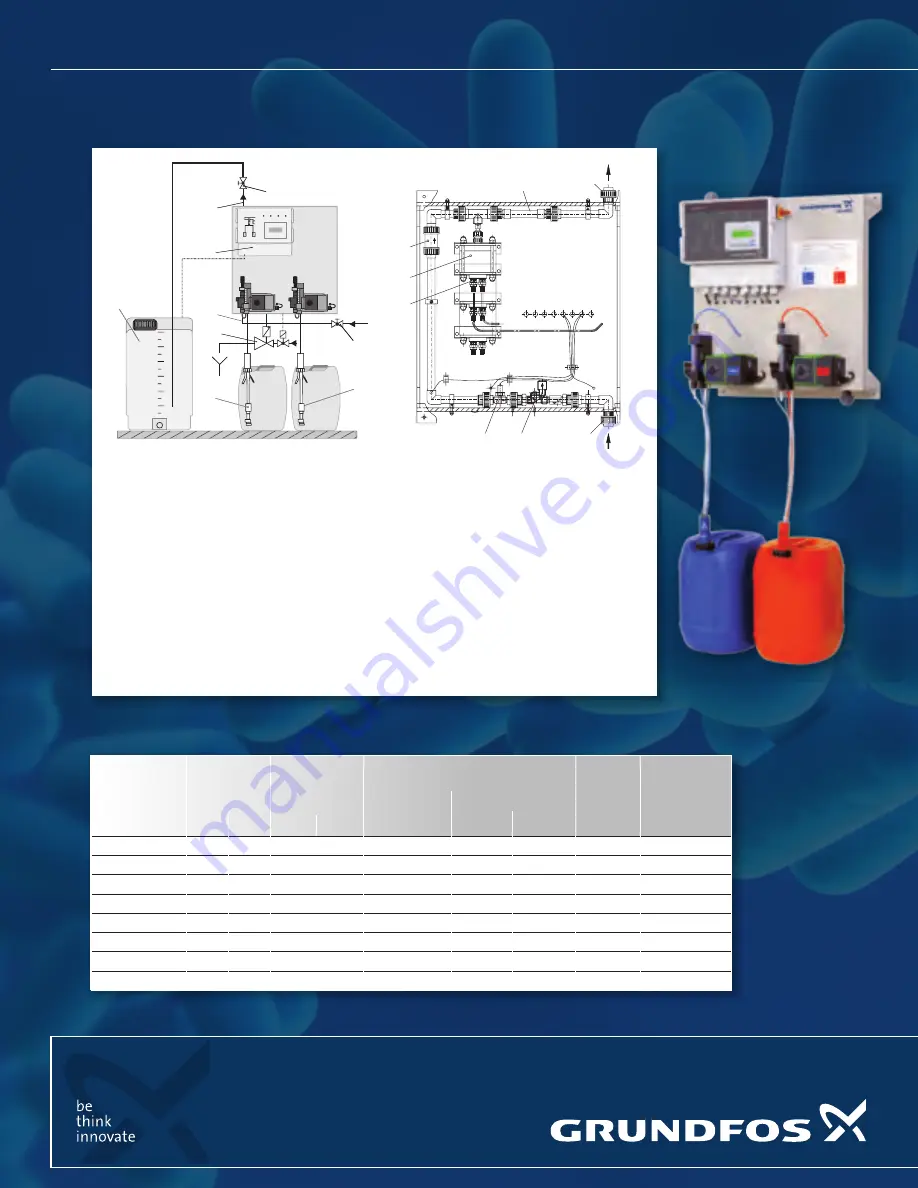
SYSTEM DESIGN

Oxiperm® 164 D Batch operation

1

 Oxiperm® 164 D electronics

2

 Connection for bypass water input

3

 Connection for the ClO2 solution line  

output to the injection unit

4

 Suction line for the HCl dosing pump

5

 Suction line for NaClO2 dosing pump

6

 Shutt-off valve (by customer)

7

 Shut-off valve (by customer)

8

 Exhaust system for supporting rack (optional)

9

 Dilution tank with level monitoring (optional)

for batch operation

10

 Solenoid valve

11

 Flow meter

12

 Precursor check valves

13

 Reaction chamber

14

 Ball check valve

15

 Back pressure valve

HCl

NaClO

2

ClO

2

9

3

6

1

8

5

4

7

2

P

A

P

A

14

13

12

11

10

2

3

15

ClO

2


preparation 

capacity

p

max  


[bar]

Consumption of 

components 

[l/h]

Consumption of bypass water [l/h] 

(input pressure < p

max

)

Weight

Type

continuous 

operation

batch operation *)

0.5 - 2 g/l

2 - 3.3 g/l

[kg]

[g/h]

50 Hz

60 Hz

HCl

NaClO

2

30

10

10

0.7

420

14

14 - 7.7

33

164-030D (DFI)

120

9

6

2.9

420

55

55 - 31

34

164-120D (DFI)

220

7

7

5.2

420

100

100 - 56

34

164-220D (DFI)

350

9

9

8.3

420

160

160 - 89

57

164-350D

700

9

9

16.5

900

320

320 - 179

62

164-700D

1000

9

9

24

900

450

450 - 258

66

164-1000D

1500

9

9

35

900

680

680 - 383

76

164-1500D

2000

9

6

48

900

900

900 - 517

82

164-2000D

grundfos 

Oxiperm batch mOde 

quick reference guide

L-DIS-SL-01.04-13.indd   1

4/11/2013   2:24:12 PM

Summary of Contents for Oxiperm 164 D

Page 1: ...noid valve 11 Flow meter 12 Precursor check valves 13 Reaction chamber 14 Ball check valve 15 Back pressure valve HCl NaClO2 ClO2 9 3 6 1 8 5 4 7 2 P A P A 14 13 12 11 10 2 3 15 ClO2 preparation capacity pmax bar Consumption of components l h Consumption of bypass water l h input pressure pmax Weight Type continuous operation batch operation 0 5 2 g l 2 3 3 g l kg g h 50 Hz 60 Hz HCl NaClO2 30 10 ...

Page 2: ...e Bypass lIne Venting the HC1O2 Venting the NaC1O2 Venting the H2O Pump Main Menu Main Menu Main Menu Main Menu Service Mode F3 Service Mode F3 Service Mode F3 Service Mode F3 Venting F1 Venting F1 Venting F1 Venting F1 Bypass Line F1 HC1 Pump F2 NaC1O2 Pump F3 H2O Pump F1 SYSTEM INFORMATION CHECKING STATUS DISPLAYING INFORMATION Main Menu Main Menu Logbook F3 Active alarms F2 SYSTEM CHOICE Main M...

Page 3: ...ey to cancel switch over to submenu Item10 Display 4 line Item11 Master switch with EMERGENCY STOP function Item12 LED for alarms LED on or flashing with alarm present Item13 Display of automatic or manual mode LED flashes manual control LED on automatic control Item14 LED for remote on off mode LED flashes remote on off by MIN contact for main water LED on remote on off by external contact Item15...

Page 4: ...0 112 109 111 NaCl O 2 32 34 36 31 33 35 38 40 42 37 39 41 out L N PE WIRING DIAGRAM Power Supply Analog Signal Floating Outputs Inputs L N PE Common point Shield 8V 59 brown 12V 43 NC contact IN OUT GND 60 GND NO contact IN OUT IN 61 blue Dosing controller NaCIO2 IN 44 Batch tank CIO2 overflow 1 2 3 Power supply input 4 5 6 Power supply output 10 11 12 HCI dosing pump 13 14 15 NaCIO2 dosing pump ...

Reviews: