background image

SERVICE MANUAL

Zusätzlich erforder-
liche Unterlagen
für den
Komplettservice:

Additionally
required Service
Manuals for the
Complete Service:

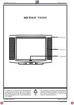
ST 170 IDTV Boston

                (9.21388-01 / GCB 4091)

SE 7088 IDTV

                (9.21389-01 / GCB 3992)

Service 
Manual

Ergänzung 
Supplement

CUC 1824

3

Sach-Nr./Part No.

72010-014.23

Sach-Nr./Part No.

72010-014.20

Service 
Manual

Sicherheit

Safety

Sach-Nr./Part No.

72010-800.00

Ergänzung 
Supplement

Änderungen vorbehalten

Printed in Germany

Service Manual Sach-Nr.  72010-014.23

Subject to alteration

VK 222 0395

Service Manual Part No. 72010-014.23

Table of Contents

Page

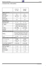
Technical Data ................................................................................ 2
Module List ...................................................................................... 3
Control Unit 29501-080.96 .............................................................. 4
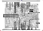
Chassis Board (Component side) ................................................... 5
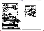
General Circuit Diagram ................................................................. 7
Video Module 29504-165.69 ......................................................... 11
Focusing Board 29305-025.20 ...................................................... 14
Chassis Board (Solder side) ......................................................... 15
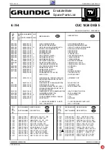
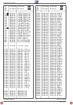
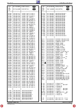
Spare Parts List ............................................................................ 17

Inhaltsverzeichnis

Seite

Technische Daten ........................................................................... 2
Modulübersicht ................................................................................ 3
Bedieneinheit 29501-080.96 ........................................................... 4
Chassisplatte (Bestückungsseite) ................................................... 5
Gesamtschaltplan ........................................................................... 7
Video-Baustein 29504-165.69 ...................................................... 11
Focussierplatte 29305-025.20 ...................................................... 14
Chassisplatte (Lötseite) ................................................................ 15

For this TV set the Service Manual CUC 1822/23/52 is applicable.
This Manual contains the differences and the additionally fitted modules
of the TV receivers.
The individual modules and the relevant part numbers are listed in the
table on page 3.
Basic instructions for servicing are given in the:
– Safety Instructions (Part No. 72010-800.00)
– Service Manual CUC 1822/23/52 (Part No. 72010-014.20)
– 1st Supplement CUC 1822/24/82/93 (Part No. 72010-014.21)
– 2st Supplement CUC 1800/22 (Part No. 72010-014.22)

Für dieses Gerät gilt das Service Manual CUC 1822/23/52.
Dieses Manual beinhaltet die Unterschiede bzw. zusätzlichen Bestük-
kungen der Geräte.
Die Bausteinbestückung und die Sachnummern der einzelnen Bau-
steine entnehmen Sie bitte der Tabelle auf Seite 3.
Grundlage für den Service sind:
– Sicherheitsvorschriften (Sach-Nr. 72010-800.00)
– Service Manual CUC 1822/23/52 (Sach-Nr. 72010-014.20)
– 1. Ergänzung CUC 1822/24/82/93 (Sach-Nr. 72010-014.21)
– 2. Ergänzung CUC 1800/22 (Sach-Nr. 72010-014.22)

GB

D

1+2

Sach-Nr./Part No.

72010-014.21
72010-014.22

Summary of Contents for CUC 1824

Page 1: ... 5 Gesamtschaltplan 7 Video Baustein 29504 165 69 11 Focussierplatte 29305 025 20 14 Chassisplatte Lötseite 15 For this TV set the Service Manual CUC 1822 23 52 is applicable ThisManualcontainsthedifferencesandtheadditionallyfittedmodules of the TV receivers The individual modules and the relevant part numbers are listed in the table on page 3 Basic instructions for servicing are given in the Safe...

Page 2: ... NTSC 4 43MHz PAL SECAM NTSC 4 43MHz Musikleistung Music power 2 x 25W 2 x 25W Anschlüsse Front Connections Front Kopfhörer Headphones Stereo 3 5mm Klinkenbuchse Lautstärke regelbar individuelle Tonkanalwahl bei 2 Ton Empfang Stereo 3 5mm jack socket adjustable volume individua channel selection with dual sound broadcasts Video IN Cinch FBAS Cinch FBAS Anschlüsse Rückwand Connections Rear Panel Eu...

Page 3: ...29305 160 05 15 Bildrohrplatte CRT Panel 29305 022 37 29305 022 37 Bedieneinheit Anzeigeeinheit Control Unit Display 29501 080 96 29501 080 96 Feature Box 29504 103 32 29504 103 32 Ost West Baustein East West Module 29504 107 93 29504 107 93 Netzentstörplatte Mains Interference Elimination Board 29304 050 95 29304 050 95 Abstimmbaustein Tuning Module 29504 103 63 65 29504 103 63 65 Video Baustein ...

Page 4: ...5 6n C1821 L R 1 2 3 1 2 3 4 SV CHROMA S VHS FBAS VIDEO S VHS K 470p C1826 K 470p C1827 2 2u 100V C1828 2 2u 100V C1829 470 R1827 470 R1826 H H H H H H H H S S S S 5V D 5V D 5V D 5V D M M M M M M M M M M M H H H H A A A A A DRUCK 29304 706 50 081 73 KEYBOARD 29501 081 73 VERS MOD SYNTONISATION AL MOD DE SINTONIA AL MOD SINTONIA TO TUNING MODULE ZUM ABSTIMMBAUSTEIN DRUCK 29304 702 96 080 96 ST1 4 S...

Page 5: ...DIG Service 4 6 Chassisplatte Chassis Board 1 5 7 11 12 14 10 8 6 4 2 5 3 5 7 A B C D E F G H I K L 21 22 L573 18 16 15 19 17 20 20A 14 10 12 11 31 13 34 32 24 27 26 25 23 37 37A 40 39 38 41 36 35 28 29 30 8 9 7 33 6 4 1 3 2 R654 R673 R683 R697 Bestückungsseite Ansicht von oben Component side top view ...

Page 6: ...Schaltpläne Circuit Diagrams CUC 1824 Schaltpläne Circuit Diagrams CUC 1824 Gesamtschaltplan General Circuit Diagram 4 7 GRUNDIG Service 4 8 GRUNDIG Service ...

Page 7: ...vice 4 10 Achtung Bei Messungen auf der Fokus sierungsplatte nur ausreichend isolierte Meßleitungen und spannungsfeste Tastköpfe z B 100 1 verwenden Attention For measurements on the focus control panel use only sufficiently insulated measuring cables and test probes with adequate electric strength eg 100 1 ...

Page 8: ...Schaltpläne Circuit Diagrams CUC 1824 Schaltpläne Circuit Diagrams CUC 1824 4 11 GRUNDIG Service 4 12 GRUNDIG Service Video Baustein Video Module 29504 165 69 ...

Page 9: ...CUC 1824 Schaltpläne Circuit Diagrams CUC 1824 Schaltpläne Circuit Diagrams GRUNDIG Service 4 13 GRUNDIG Service 4 14 Focussierungsplatte Focusing Board 29305 025 20 ...

Page 10: ...4 2 5 3 5 7 A B C D E F G H I K L 21 22 L573 18 16 15 19 17 20 20A 14 10 12 11 31 13 34 32 24 27 26 25 23 37 37A 40 39 38 41 36 35 28 29 30 8 9 7 33 6 4 1 3 2 R654 R673 R683 R697 Lötseite Ansicht von unten Solder side bottom view Chassisplatte Chassis Board 4 15 GRUNDIG Service 4 16 GRUNDIG Service ...

Page 11: ...2 MONTAGECLIP T420 421 IC410 610 ASSEMBLY CLIP 688 678 690 T504 572 D571 572 671 667 691 676 681 WW 29303 153 13 MONTAGECLIP IC688 678 690 T504 MOUNTING CLIP 0014 000 29303 153 01 MONTAGECLIP IC688 ASSEMBLY CLIP 0015 000 29303 156 08 GLIMMERSCHEIBE T420 421 IC410 MICA LAMINATION 610 688 678 690 T504 572 D571 572 671 667 691 676 681 0015 100 29303 156 20 WAERMELEITFOLIE IC688 678 690 T504 HEAT COND...

Page 12: ...LS 4148 CD 7696 8325 004 148 SMD DIODE LS 4148 CR 7501 8706 297 049 R CHIP 1206 100 OHM 5 CR 7502 8706 297 089 R CHIP 1206 4 7 KOHM 5 CR 7504 8706 297 009 R CHIP 1206 2 2 OHM 5 CR 7505 8706 100 041 R CHIP 0805 47 OHM 5 CR 7506 8706 297 093 R CHIP 1206 6 8 KOHM 5 CR 7507 8706 297 080 R CHIP 1206 2 KOHM 5 CR 7508 8706 297 093 R CHIP 1206 6 8 KOHM 5 CR 7509 8706 297 000 R CHIP 1206 JUMPER CR 7510 870...

Page 13: ... 5 CR 7697 8706 297 145 R CHIP 1206 1 MOHM 5 CR 7698 8706 297 054 R CHIP 1206 160 OHM 5 CR 7699 8706 297 053 R CHIP 1206 150 OHM 5 CT 7501 8301 002 858 SMD TRANS BC 858 A CT 7505 8301 000 848 SMD TRANS BC 848 CT 7560 8301 000 858 SMD TRANS BC 858 CT 7565 8301 006 848 SMD TRANS BC 848 C CT 7570 8301 000 848 SMD TRANS BC 848 CT 7575 8301 000 848 SMD TRANS BC 848 CT 7590 8301 004 848 SMD TRANS BC 848...

Page 14: ...M R 502 8705 269 005 MOW AX 0617 GA 1 5 OHM R 504 8730 149 039 DRW 4 ST 39 OHM 5 R 523 8705 269 257 MOW AX 0617 GA 220 OHM R 524 8735 003 022 DW 0 22 OHM 10 R 525 8735 003 033 DW 0 75W 0 33 0HM 10 R 528 8705 221 225 MOW AX 0411 GA 10 OHM R 534 8705 221 225 MOW AX 0411 GA 10 OHM R 551 8705 610 133 MOW AX 0617 330 KOHM 5 R 552 8705 610 133 MOW AX 0617 330 KOHM 5 R 553 8705 610 133 MOW AX 0617 330 KO...

Page 15: ...OOK 0024 000 09246 191 75 ENTMAGNETISIERUNGSSPULE DEGAUSING COIL 0025 000 8300 030 436 BILDR A 66 EAK 71X44 PHI PICT TUBE A 66 EAK 71X44 0030 000 29501 080 96 BEDIENEINHEIT DIGI 5 CONTROL UNIT DIGI 5 0030 100 29303 168 05 CINCHBUCHSE 3 FACH CHINCH SOCKET 0030 200 29303 390 42 KOPFHOERERBUCHSE STEREO HEADPHONE SOCKET STEREO 0030 600 29703 291 32 NETZSCHALTER POWER SWITCH 0030 700 29703 357 01 4 TAS...

Page 16: ...se gemäß dem Service Manual Sicherheit Sach Nummer 72010 800 00 sowie zusätzlich dieeventuellabweichenden landesspezifischen Vorschriften The regulations and safety instructions shall be validasprovidedbythe Safety ServiceManual part number 72010 800 00 as well as the respective national deviations 1 29625 720 01 1 3 29633 410 01 1 1 29602 603 51 BOSTON ST 170 IDTV ...

Page 17: ...0 29303 168 05 CINCHBUCHSE 3 FACH CHINCH SOCKET 0030 200 29303 390 42 KOPFHOERERBUCHSE STEREO HEADPHONE SOCKET STEREO 0030 300 29703 291 32 NETZSCHALTER POWER SWITCH 0030 400 29703 357 01 4 TASTSCHALTER KEYBOARDPLATE TACT SWITCH KEYBOARD PCB 0032 000 29633 250 01 TASTENKNOPF NETZ KEY BUTTON 0034 000 29501 591 01 TASTENSATZ MIT RAHMEN KEYS SET WITH FRAME 0046 000 29633 437 01 ABDECKUNG COVER 0049 0...

Page 18: ...rvice ÄNDERUNGEN VORBEHALTEN SUBJECT TO ALTERATION 1 29625 718 01 1 3 29633 410 01 1 1 29602 603 51 SE 7088 IDTV Änderungen vorbehalten Printed in Germany Service Manual Sach Nr 72010 014 23 Subject to alteration VK 222 0395 Service Manual Part No 72010 014 23 ...

Reviews: