Warning:
Before commencing work ensure that the negative terminals from the main and auxiliary
batteries have been disconnected.
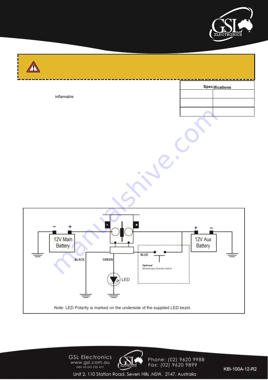
Wiring Instructions
1.
Mount the isolator high up in the engine bay away from moisture and any source
of external heat and
sources. e.g
Fuel Lines, Exhaust systems.
2.
Scratch away the paint from the body surface and earth the black wire onto the
body.
3.
Connect the main battery terminal of the solenoid to the positive terminal of the
main battery using 6B&S cable.
4.
Connect the auxiliary battery terminal of the solenoid to the positive terminal of the auxiliary battery using
6B&S cable.
5.
Ensure that the auxiliary battery is correctly earthed using a minimum 3B&S cable.
6. (Optional)
Connect the
blue wire
to Auxillary Battery Positive via a momentary switch for manual override. If
you do not use this option, ensure that it is secured away from ground or + voltage.
7. (Optional)
Connect the
green wire
to positive of supplied LED.
L.E.D Codes
:-
ON
: Solenoid contacts closed, normal operation.
OFF
: Solenoid contacts open, normal operation.
Flashing
: Abnormal Operating conditions. These are as follows: Low Main Battery (
Below 9.5V
), High Main Battery
(
Above 15.1V
), Solenoid Coil Shorted (Latched alarm/ requires disconnection of solenoid to clear), Excessive Solenoid Drop (
Latched alarm/requires disconection to reset) . In all cases when flashing occurs check both batteries and charging system for
faults.
Warranty Conditions:
Our products come with guarantees that cannot be excluded under the Australian Consumer Law.
The customer is entitled to a replacement or refund for a major failure and compensation for any other reasonably foreseeable loss or damage.
The customer is also entitled to have the products repaired or replaced if the products fail to be of acceptable quality and the failure does not
amount to a major failure.
Max Current
100 A
Cut In Volt
13.2 V ±1%
Cut Out Volt
12.7 V ±1%


