background image

English

CLASS

KLASSE


HDTV 1000 ASI LAN

HDTV 1001 C

Head-End Digital Modulator HDTV

GSS 

Grundig SAT Systems GmbH

Beuthener Strasse 43

D-90471 Nuremberg

Phone: 

+49 (0) 911 / 703 8877

Fax: 

+49 (0) 911 / 703 9210

E-mail: 

info@gss.de

Internet: 

http://www.gss.de

Summary of Contents for HDTV 1000 ASI LAN

Page 1: ...E HDTV 1000 ASI LAN HDTV 1001 C Head End Digital Modulator HDTV GSS Grundig SAT Systems GmbH Beuthener Strasse 43 D 90471 Nuremberg Phone 49 0 911 703 8877 Fax 49 0 911 703 9210 E mail info gss de Internet http www gss de ...

Page 2: ...ssette 11 3 2 EMC regulations 11 3 3 Connecting the cassette 12 3 4 Retrofitting a CA module 13 4 The control panel at a glance 14 4 1 Menu items 14 4 2 Control panel 14 5 Programming 15 5 1 Preparation 15 5 2 Notes on level setting 15 5 3 Programming procedure 16 Channel strips A without CA module and B 16 Channel strip A with CA module 19 5 4 Programming the cassette 20 Selecting the cassette 20...

Page 3: ...etting stuffing 33 Setting a substitute signal in the case of an incorrect input signal 34 Setting the transport stream ID and the ORGNET ID 35 Network Information Table NIT 35 Network operator identification 36 Deleting a PID 37 Renaming a PID 37 Factory reset 38 Saving settings 38 5 4 1 Operation with a CA module 39 Setting the scrambling 39 Setting the PID monitoring 40 Configuring the CA modul...

Page 4: ...Ê Ê L i ÌÊÌi iÀ ÌÕÀiÊ vÊäÊc ÊÌ Ê xäÊc Ê ÊV ÃiÊ vÊÌ iÊv À Ì Ê vÊ V i Ã Ì ÊÜ ÌÊÕ Ì ÊÌ iÊÃÞÃÌi Ê ÃÊV iÌi ÞÊ À i Ê UÊ ÃÕÀiÊÌ ÌÊÌ iÊ i i ÊÃÌ Ì Ê ÃÊ iµÕ Ìi ÞÊÛi Ì Ìi Ê Ê Ê Ê ÌÊV ÛiÀÊÌ iÊÛi Ì Ì Êà ÌÃ Ê UÊ iÜ ÀiÊ vÊà ÀÌÊV ÀVÕ ÌÃÊ Ê UÊ Ê L ÌÞÊ ÃÊ VVi Ìi Êv ÀÊ ÞÊ iÊV ÕÃi ÊLÞÊv Õ ÌÞÊV iVÌ ÃÊ ÀÊ À À ÌiÊ Ê UÊ LÃiÀÛiÊÌ iÊÀi iÛ ÌÊÃÌ À à ÊÀi Õ Ì ÃÊ Ê Õ i iÃÊ ÊÌ iÊ ÃÌ Ì Ê Ê iÀ Ì Ê vÊ Ìi ÊÃÞÃÌi Ã Ê UÊ iÊÃÌ À ÃÊ É É...

Page 5: ...odes DVB S 1 2 Ê2 3 Ê3 4 Ê5 6 Ê7 8 DVB S2 modes QPSK 1 2 Ê3 5 Ê2 3 Ê3 4 Ê4 5 Ê5 6 Ê8 9 Ê9 10 8PSK 3 5 Ê2 3 Ê3 4 Ê5 6 Ê8 9 Ê9 10 Symbol rate DVB S ÊÊ ÓÊoÊ xÊ Þ LÉà Symbol rate DVB S2 Ê äÊoÊÎäÊ Þ LÉÃ Ê n Ê äÊoÊÎ Ê Þ LÉà HF output Channels Ó ÊoÊ È Frequency range Ó äÊ âÊoÊnÈä äÊ âÊ Output level 97 dBµV Output impedance 75 Connections SAT inputs 2 F sockets HF output 1 IEC socket ASI input Ê Êà V iÌ Ê...

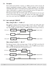
Page 6: ...UTROUTE 2 4 1 Input signal path INROUTE Menu setting A ASI 1 B ASI 2 The transport streams of the receiving stage TS A and of the ASI input TS ASI generate the transport stream 1 The transport streams of the receiv ing stage TS B and of the ASI input TS ASI generate the transport stream 2 Transport stream 1 Transport stream 2 SAT input A ASI input SAT input B Receiving stage A Receiving stage B TP...

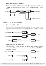
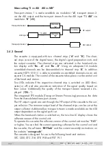
Page 7: ...tting ASI ASI Transport stream 1 is made available via modulator A ÊÌÀ Ã ÀÌÊÃÌÀi ÊÓÊÛ Ê modulator B and the transport stream from the ASI input TS ASI via the ASI output Transport stream 1 Transport stream 2 HF output ASI input Modulator B ASI output Modulator A Combiner TS ASI Menu setting 1 ASI ASI MA Ê À Ã ÀÌÊÃÌÀi Ê Ê ÃÊ iÊ Û L iÊÛ ÊÌ iÊ Ê ÕÌ ÕÌ ÊÌÀ Ã ÀÌÊÃÌÀi ÊÓÊ via modulator B and the transpo...

Page 8: ...ate if the respective channel strip is switched on LED illumi ÌiÃ Ê ÀÊ vv Ê Ê Ã Ê À Û iÊ Ê V Ì Ê vÊÌ iÊÃ ÊµÕ ÌÞÊL Ãi Ê Ê their colour Additionally the quality of the transport stream received is dis played CN The integrated TPS module Transport Stream Processing processes the data from the demodulated transport streams The HF output signals are sent through the HF output of the cassette to the out...

Page 9: ...ÃÊ vÊÌ iÊ vviÀi ÌÊ transport streams can be assembled to a new transport stream Stuffing Ê iÊÌÀ à ÀÌÊÃÌÀi Ê ÃÊ i ÊÕà ÊÜ ÌÊ ÃÊ Ü Ê ÃÊâiÀ Ê Ì Ê ÃÊi ÃÕÀiÃÊ a steady and constant output symbol rate Changing the Transport stream and ORGNET ID The transport stream ID can be changed If the stations of a transponder are à ÌÊ Ì ÊÌ iÊÌÀ à ÀÌÊÃÌÀi ÃÊ vÊÌ iÊV i ÊÃÌÀ ÃÊ Ê Ê Ê iÊ vÊÌ iÊL Ì Ê transport streams a...

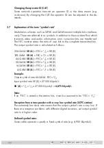
Page 10: ... The output symbol rate is calculated as follows 256 QAM SR A FEC x 1 4 x SR E 128 QAM SR A FEC x 2 7 x SR E 64 QAM SR A FEC x 1 3 x SR E 32 QAM SR A FEC x 2 5 x SR E 16 QAM SR A FEC x 1 2 x SR E 4 QAM SR A FEC x 1 1 x SR E Example Ê ÕÌ ÕÌÊÃÞ L ÊÀ ÌiÊÈ FEC 3 4 Ê ÕÌÊÃÞ L ÊÀ ÌiÊ Ê ÊrÊÓÇ xääÊkSymb s SR A 3 4 x 1 3ÊÝÊÓÇ xääÊkSymb s 6 875 kSymb s Note Ê vÊ Êº Ê ÃÊÃÌ Ìi Ê ÊÌ iÊÃÌ Ì Ê ÃÌÃ Ê ÌÊV ÊLiÊ ÃÃÕ ...

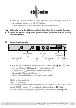
Page 11: ...ard and the HF bus bar Ê UÊ ÃÌi ÊÌ iÊV ÃÃiÌÌiÊÜ Ì ÊÌ iÊÃVÀiÜÃÊ1 0 CASSETTE CASSETTE CASSETTE CASSETTE CASSETTE CASSETTE CASSETTE CASSETTE CASSETTE CASSETTE CASSETTE CASSETTE MESSAUSGANG A ACHTUNG VordemCassettenwechsel unbedingtNetzsteckerziehen CAUTION Beforechangingcassettesremove mainsplug 3 2 EMC regulations To comply with the current EMC regulations it is necessary to connect the lines leadin...

Page 12: ...assette RS232 7 Slot for a CA module 6 LAN 3 ASI output 5 SAT input A 2 ASI input 4 SAT input B 1 Ê UÊ Plug the SAT input cables into the SAT input sockets SAT input A 2 chan nel strip A and SAT input B 1 channel strip B LAN socket 3 intended for additional functions Ê UÊ iVÌÊÌ iÊ ÊÃ V iÌÃÊ4 and 5 Ê U Connect the head end station to the mains power supply Slot for a CA module 6 RS 232 socket 7 The...

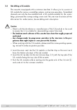
Page 13: ... it is suitable for descrambling several channels The hardware and software of this cassette have been thoroughly prepared and tested Any changes made by programme providers to the structures in the pro gramme data might impair or even prevent this function Ê qÊ 7 i ÊÜ À ÊÜ Ì ÊÌ iÊ Ê Õ i Ê i ÃiÊÀi ÊÌ iÊV ÀÀiÃ Ê iÀ Ì ing manual from the respective provider Ê UÊ ÃiÀÌÊÌ iÊà ÀÌÊV À into the CA module ...

Page 14: ...ut channel output frequency Output level LNB oscillator frequency Input symbol rate Input frequency Station filter QAM modulation Stuffing Substitute signal Transport stream and ORGNET ID Network Information Table NIT Network operator identification Deleting a PID Renaming a PID Factory reset 4 2 Control panel The key pad on the head end station is used to scroll through the menus and menu items o...

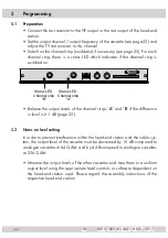
Page 15: ...annel strip B Status LED Channel strip A Ê UÊ ViÊÌ iÊ ÕÌ ÕÌÊ iÛi ÃÊ vÊÌ iÊV i ÊÃÌÀ ÃʺA and B if the difference in level is 1 dB page 25 5 2 Notes on level setting In order to prevent interference within the head end station and the cable sys Ìi ÊÌ iÊ ÕÌ ÕÌÊ iÛi Ê vÊÌ iÊV ÃÃiÌÌiÊ ÕÃÌÊLiÊ iVÀi Ãi ÊLÞÊ äÊ ÊV Ài ÊÌ Ê ÕiÊV ÃÃiÌÌiÃÊ ÌÊÈ Ê Ê ÊLÞÊ Ê ÊV Ài ÊÌ Ê ÕiÊV ÃÃiÌÌiÃÊ at 256 QAM Ê UÊ i ÃÕÀiÊÌ iÊ ÕÌ...

Page 16: ...e A Line B B A Ein On BE Remote please wait V 41 Box 4 V 12 DVBS2 TPM Bx 1A C5 12 S3 24 TWIN SAT C07 Bx 1A C5 12 S3 24 TWIN SAT C07 Böx 4 C5 12 S3 24 TWIN SAT C07 Bx 5A BD3 DVBT DVBT C09 t 10 s Bx 4 A B ASI 1 INROUTE ASI 2 A ASI 1 B ASI 2 A B ASI 1 ASI 2 A ASI 1 A ASI 2 1 ASI ASI MA 2 ASI ASI MB ASI ASI Bx 4 1 ASI OUTROUTE ASI MA Bx 4 108000 KBits ASI RATE 188 204 positive negativ continuous burst...

Page 17: ...tion Å Ï 02 19 Bx 4B TV SWF3 Programme entfernen hinzufügen Removing activating stations nächster Service Programm next service station Å Ï 01 10 ASI TV Programme entfernen hinzufügen Removing activating stations nächster Service Programm next service station Å Ï M M M M M M M M M M M M Bx 4A SR 6900 6325 STUFFING Bx 4A Null Packets FAILURE Bx 4A 64 QAM QAM normal Å Ï Å Ï Å Ï 4 256 normal inverse ...

Page 18: ...IT Make Bx 4A 0x0001 0100 TS ONID off on off Å Å on off Make Bx 4A PID 0x0000 DROP off Bx 4A 0XDE00 CAT ID off Å Ï Bx 4A Defaults FACTORY Bx 4A STORE FACTORY M on off Å Ï Å Ï on off Å Ï auf Werkseinstellung zurücksetzen und speichern reset to factory defaults and store Å Ï on off Å Ï Bx 4A 0x0000 0000 REMAP off Page 16 Page 16 ...

Page 19: ...odul The information displayed is dependent on the CA module used Bx 4A 01 03 Information MENU Bx 4A TV X 04 09 X entschlüsseln descrambling 0 nicht entschlüsseln no descrambling X 0 nächster Service next service Bx 4A PID Check CA on Å Ï on off M Å Ï D Bx 4A scramble CA scramble descramble C scramble descramble Page 17 Page 17 only HDTV 1001 C ...

Page 20: ...e display shows the software version e g V 41 The processor reads the cassettes data approximately 10 seconds Selecting the cassette Ê UÊ i iVÌÊÌ iÊcassette you want to programme e g Box 4 by repeatedly press ing the button if necessary The display shows e g the menu Box 4 DVBS2 TPM V12 Box 4 stands for slot 4 DVBS2 TPM Type of cassette V 12 Software version of the cassette Ê UÊ ÀiÃÃÊÌ iÊ button T...

Page 21: ... In this menu you define the signal path of the output transport streams Menu setting ASI ASI page 7 Menu setting 1 ASI ASI MA page 7 Menu setting 2 ASI ASI MB page 8 Ê UÊ 1ÃiÊÌ iÊ buttons to select the signal path wished Ê UÊ vÊÞ ÕÊ Ê ÌÊÜ ÌÊÌ Ê Ê ÊÃiÌÌ Ã Ê ÀiÃÃÊÌ iÊ button The Selecting the channel strip LINE menu is activated page 23 Ê UÊ ÀiÃÃÊÌ iÊ button The Setting the ASI transfer rate ASI RA...

Page 22: ... Ê V iÌÃ ÊÌ i ÀÊ À ÌÞÊ ÊÌ iÊÌÞ iÊ of transmission For this setting please take the required information from the documentation technical data of the ASI component to be connected Ê UÊ ÀiÃÃÊÌ iÊ ÊLÕÌÌ ÃÊÌ ÊÃiÌÊÌ iÊÃ âiÊ vÊÌ iÊ Ì Ê V iÌÃÊ º188 or 204 bits Ê UÊ vÊÌ iÊ À ÌÞÊ vÊÌ iÊ Ì ÊÌ ÊLiÊÌÀ Ã ÌÌi Ê ÃÊÌ ÊLiÊV i Ê ÀiÃÃÊÌ i buttons to place the cursor under pos positive standard and us ing the buttons...

Page 23: ...ÊL Ü Ì Ê vÊnÊ â Ê ÃÊ means that you can only use the channel centre frequency of the existing V i Ê À Ê ÊÌ iÊÀ iÊ vÊV i ÃÊ Ó ÊoÊ È Ê vÀiµÕi VÞÊ À ÊnÊ â Ê iÊ ÊV i Ê À Ê ÃÊÇÊ âÊ ÊÌ iÊÀ iÊ vÊÌ iÊ ÜiÀÊvÀiµÕi VÞÊL ÃÊ V i ÃÊ ÓÊoÊ Óä Ê iÀiv ÀiÊÌ iÊvÀiµÕi VÞÊÃiÌÌ Ê ÃÊÕÃi Ê iÀi Ê vÊ iÊÕÃiÃÊ Ì iÊiÝ ÃÌ ÊV i Ê À Ê vÊÇÊ âÊ ÊÌ iÃiÊV i ÊÀ ià ÊÌ ÃÊÜ ÊÀiÃÕ ÌÊ Ê ÌiÀviÀi ViÊ ÛiÀ ÊÜ Ì ÊÌ iÊnÊ âÊ ÊÃ Ê V ià ÊÌ ÕÃÊV Õà ...

Page 24: ... off Å Ï Å Ï Bx 4A 0 dB LEVEL Bx 4A 10600 MHz LNB 0 10 dB Bx 4A 12 0 dB C N 9 6 OK Anzeige Signalqualität Display Signal quality Å Ï DVB S DVB S 2 Bx 4A Filter PROGRAM off 01 10 Bx 4A TV Das Erste Programme entfernen Removing activating nächster Service Pro next service station Å Ï 02 19 Bx 4B TV SWF3 Programme entfernen Removing activating nächster Service Pro next service station Å Ï 01 10 ASI T...

Page 25: ...l back to the Selecting the channel strip menu Ê UÊ i iVÌÊÌ iÊ Ì iÀÊV i ÊÃÌÀ page 23 and set the following menu items Ê UÊ º i iVÌ ÊV i ÊÉÊvÀiµÕi VÞÊÃiÌÌ Ê iÊÓÎ Ê UÊ º iÌÌ ÊÌ iÊ ÕÌ ÕÌÊV i Ê Àʺ iÌÌ ÊÌ iÊ ÕÌ ÕÌÊvÀiµÕi VÞ Ê iÊÓ Ê UÊ Ü ÌV Ê ÊÌ iÊ Õ Ì ÀÊ vÊ iViÃà ÀÞÊ iÊÓx Ê UÊ i ÃÕÀiÊ Ê ÌiÊ Ü ÊÌ iÊ ÕÌ ÕÌÊ iÛi Ê UÊ VÌ Û ÌiÊÌ iÊ LEVEL menu of the channel strip with the higher output level Ê UÊ ÞÊ ÀiÃà n...

Page 26: ...A TV Das Erste Programme entfernen Removing activating nächster Service Pro next service station Å Ï 02 19 Bx 4B TV SWF3 Programme entfernen Removing activating nächster Service Pro next service station Å Ï 01 10 ASI TV Programme entfernen Removing activating nächster Service Pro next service station Å Ï M M M M M M M M M M Bx 4A SR 6900 6325 STUFFING Bx 4A 64 QAM QAM normal Å Ï Å Ï 4 256 normal i...

Page 27: ...has finished Ê ViÊÌ iÊ ÊÀiVi ÛiÀÊ ÃÊÃÞ V À Ãi ÊÌ ÊÌ iÊ ÕÌÊÃ Ê ÞÊ vvÃiÌÊÌ ÊÌ iÊ Ì À iÌÊvÀiµÕi VÞÊ ÃÊ Ã Þi Ê Ê â Êi ʺ 1 8 If a question mark Ê i ÀÃÊ ÊÌ iÊÃiV Ê iÊ vÊÌ iÊ Ã Þ ÊÌ iÀiÊ ÃÊ Ê input signal present Check the configuration of the antenna system and head end station as well as the preceding settings of the cassette Ê UÊ 1ÃiÊ to position the cursor under the digit to be set of the frequency ...

Page 28: ... occur 3 If OK Ê ÃÊÃ Ü ÊÌ iÊÃ ÊÌ Ê ÃiÊÀ Ì Ê ÃÊ If a value 5 is shown under 2 the display changes from OK to In this case test the input signal Ê Ê Ì ÊÌ ÊÌ iÊ V Ì ÀÊ ÊÌ iÊ Ã Þ ÊÌ iÀiÊ ÃÊ Ã Ê ÊÃÌ ÌÕÃÊ ÊÜ V Ê indicates the quality of the received transport stream LED indicator Indication Green Signal quality is good Yellow Signal quality is poor Red No signal Off The channel strip modulator is switch...

Page 29: ...for the station filter is off In this menu you define the sta tions received to be transmitted If stations are activated the output symbol rate increases If the station filter is switched off factory default all stations of the transport stream passes the station filter As soon as the station filter is activated all sta tions are inactive and can be added to the transport stream selectively The fi...

Page 30: ... being displayed Das Erste Station name Bx 4A 11835 0 6 FREQ CN 14 Å Ï Bx 4A 12 0 dB C N 9 6 OK Anzeige Signalqualität Display Signal quality Bx 4A Filter PROGRAM off 01 10 Bx 4A TV Das Erste Programme entferne Removing activatin nächster Service Pr next service station Å Ï 02 19 Bx 4B TV SWF3 Programme entferne Removing activatin nächster Service Pr next service station Å Ï 01 10 ASI TV Programme...

Page 31: ... Ì Ê À iÀ ÊÌ i ÊÕÃiÊ to activate indicated by or to remove them Factory default All stations are deactivated Ê U Press the button Ê UÊ iÌÊÌ iÊÃÌ Ì Êv ÌiÀÃÊ vÊV i ÊÃÌÀ ʺB and ASI in the same way as chan nel strip A Ê U To save changes and to activate the station filter press the button The filter is activated The display shows PROGRAM Filter on Ê p Ê vÊÃÌ Ì ÃÊ ÀiÊ VÌ Û Ìi ÊÌ iÊV ÀÀiÃ Ê ÃÊ Õ ÊÛ i Ê...

Page 32: ...iÊ À L i à ÊÀiVi Ì Ê vÊ the converted output signal can be affected Bx 4A Filter PROGRAM off 01 10 Bx 4A TV Das Erste Å Ï 02 19 ASI TV ORF2 Å Ï Å Bx 4A 27500 SYMBOL DVB S Bx 4A 11835 0 6 FREQ CN 14 Å Ï Å Ï Å Ï Bx 4A 10600 MHz LNB Bx 4A 12 0 dB C N 9 6 OK Anzeige Signalqualität Display Signal quality Å Ï DVB S DVB S 2 Bx 4A Filter PROGRAM off 01 10 Bx 4A TV Das Erste Programme entfernen Removing ac...

Page 33: ...ÀÊ the symbol rate of the ASI input signal cannot be measured The ASI input signal therefore must be built in such a way so that the output symbol rate Number 1 is not exceeded The symbol rates of the transport streams built by the cassette can be measured at the setting OUTROUTE ASI ASI and be displayed in the respective channel strip next service station 01 10 ASI TV Programme entfernen Removing...

Page 34: ... set whether a QAM signal filled with Null Packets Ê a QAM signal filled with null packets and self made tables Tables or a Single Carrier signal should be provided as an output signal whenever an incorrect input signal occurs Self made tables are transmitted furthermore Ê U Use the buttons to set the output signal required Ê UÊ ÀiÃÃÊÌ iÊ button The Setting the transport stream ID and the ORGNET I...

Page 35: ...Ã ÊiÌV Ê ÌÊ ii ÃÊvÀ Ê ÊÌ iÊo QAM cassettes in order to gener ate the cable NIT This process may take a few seconds Ê Ê i ÊÌ iÊ Ê ÃÊ i iÀ Ìi Ê i Ê ÊÃi ÌÊÌ Ê Êo QAM cassettes The Ì iÀÊo Êcassettes also add this new cable NIT The status of all M M M M M M M M M Bx 4A SR 6900 6325 STUFFING Bx 4A Null Packets FAILURE Å Ï Å Ï Null Packets Single Carrier Bx 4A off NIT Make Bx 4A 0x0001 0100 TS ONID off o...

Page 36: ...ed page 37 CAT is to be changed The network operator e g requires that you set the operator ID of the visAvision transponder to 2 Ê UÊ Use the buttons to position the cursor under the digit to be set Ê UÊ 1ÃiÊ to change the operator ID from 0xDE00 to 0xDE02 Ê UÊ 1ÃiÊÌ iÊ button to position the cursor under off ÊÌ i ÊÕÃiÊ to ac tivate the new CAT on The menu display switches to modified If you try ...

Page 37: ...iÊÌ iÊ buttons to place the cursor under the respective digit of the hexadecimal number of the new PID 0000 Ê UÊ iÌÊÌ iÊ iÝ iV Ê Õ LiÀÊÕÃ Ê Ê UÊ 1ÃiÊ to set the cursor to off and switch to on rename using the buttons M M M M M M B A Bx 4A off NIT Make Å Å on off Make Bx 4A PID 0x0000 DROP off Bx 4A 0XDE00 CAT ID off Å Ï Bx 4A Defaults FACTORY Bx 4A STORE FACTORY M on off Å Ï Å Ï on off Å Ï auf Wer...

Page 38: ...ÊÜ ÊLiÊÀiÌÕÀ i ÊÌ ÊÌ iÊ i ÕÊ Ìi Ê Selecting the channel strip via B without saving the factory defaults page 23 If necessary set channel strip B Saving settings Ê UÊ ÀiÃÃÊÌ iÊ button Back to Selecting the cassette A page 20 The settings are saved Ê p Ê vÊvÕ VÌ ÃÊ vÊÌ iÊ Ê Õ iÊ ÀiÊ VÌ Û Ìi ÊÌ i ÀÊÃÌ ÌÕÃÊ ÃÊÃ Ü Ê ÊÌ iÊ second line of the display M Station filter is switched on N NIT is activated C N...

Page 39: ... page 40 Setting the scrambling With cassette HDTV 1001 C it is possible to scramble unscrambled channels 9 ÕÊV ÊÃiÌÊÜ iÌ iÀÊÞ ÕÊÜ ÌÊÌ Ê iÃVÀ L iÊÃVÀ L i ÊV i Ã Ê ÀÊÌ ÊÃVÀ ble unscrambled channels Ê UÊ 1ÃiÊÌ iÊ buttons to set scramble or descramble Ê UÊ ÀiÃÃÊÌ iÊ button In case of setting scramble The Setting the QAM modulation QAM menu is activated page 32 In case of setting descramble The Settin...

Page 40: ... i ÃiÊÀiviÀÊÌ ÊÌ iÊ iÀ Ì Ê Õ Ê vÊÞ ÕÀÊ ÀÌ VÕ ÀÊ Ê Õ i Ê iÊ relevant information is shown in the display of the head end station This may appear as a fixed display or as scrolling text according to display capabilities By pressing the button you can skip the Configuring the CA module CA menu and activate the Setting the QAM modulation QAM menu page 32 Ê UÊ ÀiÃÃÊÌ iÊ button to activate the menu of t...

Page 41: ...he CA module CA menu Ê UÊ ÀiÃÃÊÌ iÊ button The Setting the station filter Edit menu is activated Setting the station filter Ê ÊÌ ÃÊ i ÕÊÞ ÕÊÃi iVÌÊÌ iÊÃÌ Ì ÃÊÜ Ã i ÊvÀ ÊÌ iÊi V i Ê Ì ÊÃÌÀi Ê which are to be decoded The display shows e g Bx 4A TV X 04 09 Meaning of the indicators in the example Bx 4A ÊÊqÊ ÌÊ ÊV i ÊÃÌÀ ʺA TV TV channel type X The currently selected station is to descramble 04 09 Th...

Page 42: ...tial order which are to be descramble ÊÌ i ÊÕÃi to descramble X or not to descramble 0 them U Save changes and activate the station filter Ê UÊ ÀiÃÃÊÌ iÊ button The filter is activated The display shows the Configuring the CA mod ule CA menu Ê UÊ ÀiÃÃÊÌ iÊ button The Setting the QAM modulation QAM menu is activated page 32 Bx 4A Menu CA Edit Bx 4A 01 03 Information MENU Bx 4A TV X 04 09 X 0 Å Ï M ...

Page 43: ...compliance with current EMC regulations securely Ê UÊ iVÕÀi ÞÊÌ Ìi ÊÌ iÊV L iÊV iVÌ ÃÊÕÃ Ê Êappropriate open ended spanner Ê UÊ i ÃÕÀiÊÌ iÊ ÕÌ ÕÌÊ iÛi ÃÊ vÊÌ iÊ Ì iÀÊV ÃÃiÌÌiÃÊ ÊÌÕ iÊÌ i ÊÌ Ê ÊÕ v À Ê output level using the appropriate level controls or software dependent on the head end station used Please regard the assembly instructions of the respective head end station Ê UÊ Õ ÌÊÌ iÊvÀ ÌÊV ÛiÀ...

Page 44: ...498 00 C 25 506 00 C 26 514 00 C 27 522 00 C 28 530 00 C 29 538 00 C 30 546 00 C 31 554 00 C 32 562 00 C 33 570 00 C 34 578 00 C 35 586 00 C 36 594 00 C 37 602 00 C 38 610 00 C 39 618 00 C 40 626 00 C 41 634 00 C 42 642 00 C 43 650 00 C 44 658 00 C 45 666 00 C 46 674 00 C 47 682 00 C 48 690 00 C 49 698 00 C 50 706 00 C 51 714 00 C 52 722 00 C 53 730 00 C 54 738 00 C 55 746 00 C 56 754 00 C 57 762 ...

Page 45: ...Alterations reserved Technical data E O E GSS GmbH V12 07122009 Service Phone 49 0 911 703 2221 Fax 49 0 911 703 2326 Email service gss de ...

Reviews: