background image

Assembly Instruction

PADA 5100

Summary of Contents for PADA 5100

Page 1: ...Assembly Instruction PADA 5100 ...

Page 2: ... 4 2 Control panel 12 5 Programming 13 5 1 Programming procedure 13 5 2 Programming the cassette 16 Selecting the cassette 16 Ethernet parameters 17 Hardware IP address 17 Address range 18 Address of the gateway 18 UDP port 19 Multiplex mode 19 SID standard 20 SID range 21 Output parameters 21 ASI transmission rate 22 ASI options 22 LAN data rate 23 Output IP address 24 Target MAC address 24 Switc...

Page 3: ...stream ORGNET ID 33 NIT 33 Refresh the tables 34 Output data rate 35 LAN check 35 Factory reset 36 Saving settings 36 Cascading 37 at SID standard 16 Bit 37 at SID standard 8 Bit 39 6 PSW 1000 Options 41 6 1 Menu Settings 41 Settings window Edit menu 44 6 2 Menu Filter 45 Multiplex mode manual 46 Activating Stations services 46 Changing SIDs PIDs manually only in Multiplex mode manual 46 7 Final p...

Page 4: ...ts No liability is accepted for any damage caused by faulty connections or inappropriate handling Observe the relevant standards regulations and guidelines on the installa tion and operation of antenna systems The standards EN DINEN50083 resp IEC EN DINEN60728 must be observed For further information please read the assembly instructions for the head end station used Test the software versions of ...

Page 5: ...0 2 General information 2 1 Packing contents 1 Cassette PADA 5100 1 LAN cable 6 BNC cable 1 Brief assembly instructions 1 Messprotokoll 2 2 Meaning of the symbols used Important note General note Performing works ...

Page 6: ...tocols UDP User Data Protocol RTP Real Time Transport Protocol ASI interfaces ASI Asynchronous Serial Interface Standard DIN EN 50083 9 Format MPEG ISO IEC 13818 1 Impedance 75 Ω Max data rate 108 MBit s Level input output 800 mVPP 10 Return loss input 17 dB 5 270 MHz Connections LAN 1 RJ 45 socket ASI inputs 5 BNC sockets 75 Ω ASI output 1 BNC socket 75 Ω Connection strip 10 pin for supply voltag...

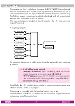
Page 7: ...AN 6 227 40 50 6 LAN 5 227 40 50 5 LAN 4 227 40 50 4 LAN 3 227 40 50 3 LAN 2 227 40 50 2 LAN1 227 40 50 1 For operating the cassette in a LAN network it can be assigned its own hardware IP address Two IP address ranges are used Hardware IP addresses menu ETHERNET which are used to connect the cassettes in the network e g 192 168 0 x IPTV IP addresses menus OUT IP IP INPUT which are used to send an...

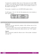
Page 8: ...nd stations Five LEDs page 11 6 8 0 indicate by their colour whether an input signal is present LED colour Indication Green Signal present Red no Signal 2 5 Software query Control unit If necessary you can activate the indication of the software version of the control unit manually Press any two keys on the control unit of the head end station simultaneously until the display goes dark and the sof...

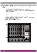
Page 9: ...n that vibrates in a similar way Before installing or changing a cassette unplug the power cable from the mains power socket Remove the fastening screws 1 of an unoccupied slot from the bracket of the head end station Insert the cassette in this slot and push it into the housing Align the cassette and apply slight pressure to connect it to the connections of the board and the HF bus bar Fasten the...

Page 10: ...eading in and out for the 19 cabinet are made using cable terminals CLASS KLASSE The attenuation of shielding of the connection lines for ASI and antenna must meet the requirements for Class A Insert the required number of cable terminals in the openings provided in the head end station or in the 19 cabinet Tighten the nuts on the cable terminals until the teeth on the lock washer have penetrated ...

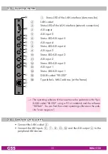
Page 11: ... LED ASI input 3 ASI input 2 Status LED ASI input 2 ASI input 1 Status LED ASI input 1 D SUB socket RS 232 Type label MAC address at the frame The operating software of the cassette can be updated via the 9 pin D SUB socket RS 232 using a PC or notebook and the software BE Flash You can find the current operating software on the web site www mygss eu 3 4 Connecting the cassette Connect the LAN soc...

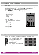
Page 12: ...owing main menu items Ethernet parameter Multiplex mode SID standard SID offset Output parameter Input parameter Transport stream and ORGNET ID NIT Refresh tables Displaying the data rate LAN check Factory reset 4 2 Control panel The key pad on the head end station is used to scroll through the menus scrolls forward through the menus select parameters in the menus set values initiate actions selec...

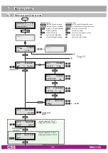
Page 13: ...Bx 4 OUTPUT Bx 4 ASI RATE Bx 4 MUX MODE manual Bx 4 0xxx SID OFFSET nur bei Auswahl 16 Bit only with selection 16 Bit nur bei Auswahl fixed only with selection fixed 16 Bit default 8 Bit US Bx 4 16 Bit SID NORM default Bedienhinweise blättert Menüs vorwärts blättert Menüs rückwärts wählen die Eingabeposition wählt Untermenü stellen Werte ein speichert alle Eingaben 1 zeigt die Eingabeposition Oper...

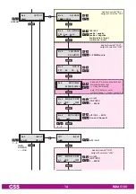
Page 14: ...FILTER IN 1 LAN INPUT ASI LAN ASI LAN Bx 4 227 40 50 6 OUT IP Bx 4 LAN OUTPUT Bx 4 on UDP MODE PORT 1234 on off UDP RTP 0 65535 Bx 4 7 off PKTS FEC off 10 9 20 19 Annex A Annex B 1 7 Bx 4 108000 KBits ASI RATE 188 204 positiv negativ positive negative kontinuierlich burst continuous burst 2 80MBits auto Bx 4 188 pos cont ASI OPTION 0xxx nur wenn IP Adresse außerhalb des Multicastbereichs liegt Uni...

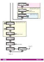
Page 15: ... transparent nicht bei MUX MODE transparent not with MUX MODE transparent nur bei Auswahl manual only with selection manual on off IN 1 227 40 50 1 IP INPUT on UDP 1234 0 65535 001 016 IN 1 TV Das Erste first all cascaded manual IN 1 all FILTER always new only Bx 4 Tables REFRESH always enable disable Bx 4 off NIT Bx 4 0x0001 0100 TS ONID Page 13 Page 13 ...

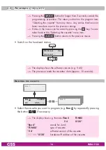
Page 16: ...urns to the previous menus Switch on the head end station BE Remote please wait V 45 t 10 s Ein On The display shows the software version e g V 45 The processor reads the cassettes data approx 10 seconds Selecting the cassette Box 4 V 4 TS MUX 0 128 Box 1 Bx 1A C5 12 S3 24 TWIN SAT C07 Böx 4 C5 12 S3 24 TWIN SAT C07 Box 5 Select the cassette you want to program e g Box 4 by repeatedly pressing the...

Page 17: ...ng DHCP of the Ethernet parameters Press the button to activate the setting options Options The Hardware IP address IP ADDR sub menu is activated Hardware IP address To operate the cassette in a network an IP address must be assigned to each IPTV cassette If a manually setting of the Ethernet parameters is selected set the IP address of the cassette in this menu If DHCP is selected the IP ADDR IP ...

Page 18: ...e buttons to place the cursor under the digit of the IP mask displayed to be set and use to set the desired IP mask Press the button The Address of the gateway IP GATEWAY sub menu is activated Address of the gateway The address of a gateway server router can be set in this menu If no gate way is used you can skip this setting Bx 4 192 168 0 1 IP GATEWAY Use the buttons to place the cursor under th...

Page 19: ...Bx 4 MUX MODE manual Use the buttons to select the desired Multiplex mode manual all programme are deactivated and must be activated in menu Station filter page 29 The SIDs remain unchanged Only if SIDs are present twice they will be changed see page 30 Using PSW 1000 it is possible the change SIDs PIDs manually page 46 fixed all SIDs will be changed see page 30 transparent Conversation from LAN A...

Page 20: ...ion The reduction to 8 bit results in a limitation to 255 of the available SIDs compared to the 65535 SIDs of the 16 bit version Then the SID range SID offset menu is skipped Bx 4 16 Bit SID Norm default Use the buttons to select the desired version Please note the following if you use the 8 bit setting As you can not set a SID offset you may either use one cassette or you have to cascade several ...

Page 21: ... several PADA 5100 are used in parallel and not cascaded Use the buttons to enter the desired offset Press the button The Output parameters OUTPUT main menu is activated Output parameters In this menu you select whether you whish to output the output transport stream via the ASI output or the LAN In addition you can set the output parameters in the submenus Bx 4 ASI OUTPUT Bx 4 LAN OUTPUT Use the ...

Page 22: ...tons to set the desired transmission rate Press the button The ASI options ASI OPTION sub menu is activated ASI options In this menu you define the size of the data packets their polarity and the type of transmission For this setting please take the required information from the documentation technical data of the ASI component to be connected 188 pos cont ASI OPTION Press the buttons to set the s...

Page 23: ... OUTPUT main menu page 21 Press the button The Input parameters INPUT main menu is activated page 27 LAN data rate In this menu you adjust the LAN output data rate ein Bx 4 LAN RATE 50 0 MBITS Press the buttons to position the cursor under the digit of the data rate to be set Using the buttons set the desired data rate 2 MBit 80 180 MBit auto The maximum data rate depends on the connected network ...

Page 24: ...ching the IP address off or on transmission protocol port number MODE PORT submenu is activated page 25 IP address out of the multicast range The Target MAC address DEST MAC submenu is activated Target MAC address This menu will only be activated if the an IP address was set out of the multicast range before Herein you can assign the Target MAC address for an Unicast transmission Point to Point co...

Page 25: ...to position the cursor under UDP Using the buttons to select the desired transmission protocol UDP The User Datagram Protocol is for the connectionless trans mission of data without acknowledgement from the receiver RTP The Real time Transport Protocol additional transmits time infor mations for runtime error correction at receiver side Setting the port number Press the button to position the curs...

Page 26: ...tity of MPEG data packets in one IP data packet 1 7 Setting 7 results the smallest overhead Setting the forward error correction Press the button to position the cursor under off In position off the forward error correction FEC is switched off Using the buttons set the value of the desired FEC off 10 9 20 19 7 10 09 AnnexB PKTS FEC Setting the transmission channel Press the button to position the ...

Page 27: ...e input parameters To skip the settings of the input parameters press the but ton The Transport stream ORGNET ID TS ONID main menu is activated page 33 Press the button The Signal source IN x INPUT submenu is activated Signal source In this menu you select the desired signal source for the selected input IN 1 LAN INPUT IN 2 ASI INPUT Use the buttons to select the desired signal source LAN or ASI I...

Page 28: ...off or on the IP address and the service referred Selecting the transmission protocol Press the button to position the cursor under UDP Using the buttons to select the desired transmission protocol UDP The User Datagram Protocol is for the connectionless trans mission of data without acknowledgement from the receiver RTP The Real time Transport Protocol additional transmits time infor mations for ...

Page 29: ...or under the digit of the IP ad dress to be set Using the buttons set the desired IP address Press the button The Station filter FILTER submenu is activated Station filter This menu is not displayed if transparent is selected in menu Multiplex mode page 19 If manual is selected in menu Multi plex mode herein only the setting manual is possible In this menu you select the stations services of the i...

Page 30: ...ted services MUX MODE manual only SIDs which are present twice will be changed MUX MODE fixed all SIDs will be changed At station filter settings all first und manual the assignment of the SIDs is done dynamically according to the following scheme SID standard 16 Bit Input 1 services 1 64 SIDs 101 164 Input 2 services 1 64 SIDs 201 264 Input 3 services 1 64 SIDs 301 364 Input 4 services 1 64 SIDs ...

Page 31: ... Services of the input transport stream will be read and then displayed with name and station type If no station is found the following message will appear in the display FILTER no Service In this case check the configuration of the antenna system and head end station as well as the previously adjusted settings for the cassette and the components connected to the ASI LAN input The display shows e ...

Page 32: ...ta stream is being received Use the buttons to call up the stations in sequential order then use to activate indicated by or to deactivate them indicated by If no station is found the display shows instead of the station name In this case check the previously adjusted settings for the cassette and the compo nents connected to the ASI LAN input Press the button You will be returned to the Input par...

Page 33: ...under the digit of the hexadeci mal number to be set Press to set the respective digit of the hexadecimal number Repeat the procedure by the quantity of the digits to be set Press the button The NIT main menu is activated NIT This menu is not displayed if transparent is selected in menu Multiplex mode page 19 Is a NIT generated via the remote control software PSW 1000 from SW V39 on the PADA 5100 ...

Page 34: ...u Multiplex mode page 19 Herein you select when the tables are refreshed Bx 4 Tables REFRESH always Use the buttons to select the desired mode always the tables are refreshed at any modification also if a station is dropped new only the tables are only refreshed if station are modified or added Press the button The Output data rate DATARATE main menu is activated ...

Page 35: ...0 MBit 100 MBit LAN 80 MBit ASI ASI RATE setting page 22 Press the button The LAN check main menu is activated LAN check Herein you can switch on or off the LAN check If enable is selected the cassette will be restarted after ca 30 seconds if no LAN input signal is present Bx 4 LAN CHECK enable Use the buttons to switch on enable or off disable the LAN check Press the button The Factory reset FACT...

Page 36: ... to the menu item Ethernet parameters ETHERNET without invoking the fac tory defaults page 17 Press the button The factory defaults are saved The display shows STORE Back to Selecting the cassette page 16 By pressing the button you will be returned to the menu item Ethernet parameters ETHERNET without invoking the fac tory defaults page 17 Saving settings Press the button Back to Selecting the cas...

Page 37: ... 21 25 Service 01 25 Service 02 Service 03 Service 04 Service 05 Service 06 Service 07 Service 08 Service 09 Service 10 Cassette 3 Cassette 1 Cassette 2 Cassette 6 Cassette 4 Cassette 5 At setting cascaded the assignment of the SIDs is done statically a defined output SID will be assigned to a defined input SID so that the SIDs of the serv ices at the output of the downstream cassette 6 will not c...

Page 38: ... 234 334 434 534 405 144 244 344 444 544 406 154 254 354 454 554 501 105 205 305 405 505 502 115 215 315 415 515 503 125 225 325 425 525 504 135 235 335 435 535 505 145 245 345 445 545 506 155 255 355 455 555 If more than one services are present at one input of the upstream cassettes cassettes 1 5 of the exam ple in the downstream cassette cassette 6 of the example the SIDs will be assigned stati...

Page 39: ...0 Services 21 25 Services 01 50 Service 02 Service 03 Service 04 Service 05 Service 06 Service 07 Service 08 Service 09 Service 10 Cassette 3 Cassette 1 Cassette 2 Cassette 6 Cassette 4 Cassette 5 At setting cascaded the assignment of the SIDs is done statically a defined output SID will be assigned to a defined input SID so that the SIDs of the serv ices at the output of the downstream cassette 6...

Page 40: ...ream cassettes cassettes 1 5 of the exam ple in the downstream cassette cassette 6 of the example the SIDs will be assigned statically accord ing to the table beside According to this table up to 6 services per input cas settes 1 5 can be proc essed Example If at input 2 of cassette 2 two services are present SID 22 is assigned to the 2nd service at the output of cassette 2 according to the dynami...

Page 41: ...r For basic operations observe the operating instruction of the PSW 1000 All modifications configurations with exception of the direct con trol via the virtual control unit be done in the PSW 1000 software first are only be hold in the RAM random access memory of the PC Final the configuration data must be sent to the plant send data 6 1 Menu Settings Herein you can perform the input and the outpu...

Page 42: ... operating instruction of the PSW 1000 The menu contains five submenus tab Line A Line E In the following figures the input fields are assigned to the corresponding menus of the control unit Section Input ASI IN 1 ASI INPUT IN 1 LAN INPUT Section Input LAN IN 1 227 40 50 1 IP INPUT IN 1 on UDP MODE PORT 1234 IN 1 LAN INPUT ...

Page 43: ... ASI OPTION Bx 4 108000 KBits ASI RATE Section Output LAN Bx 4 LAN OUTPUT 227 40 50 6 OUT IP on UDP MODE PORT 1234 7 off PKTS FEC Bx 4 0x0001 0100 TS ONID Bx 4 LAN CHECK enable Bx 4 off NIT Bx 4 LAN RATE 50 0 MBITS 223 40 50 6 OUT IP Bx 4 DEST MAC 0022B7000000 When all settings are finished send the data to the plant cas sette ...

Page 44: ... using button Import cassette and filter settings With this menu item you can import the cassette and filter settings Select menu item Edit Import cassette and filter settings Select the corresponding file and confirm with button The saved data will be imported into the programme Ethernet settings With this menu item you can perform the Ethernet settings hardware IP ad dress of the cassette Bx 4 1...

Page 45: ...rresponding input signals are present at the signal inputs of the cassette Now read out the data from the cassette to the PSW 1000 in order to see the current SIDs PIDs in menu Filter OFFSET 1xx Bx 4A PID Bx 4 16 Bit SID Norm default Bx 4 0xxx SID OFFSET Bx 4 Tables REFRESH always IN 1 all FILTER In section Input tab Service PIDs the SIDs PIDs are listed The in dividual setting of the station filt...

Page 46: ...s of all stations which shall be output The PIDs which correspond to the stations are also activated but can be deactivated again In section Overview filter settings all activated stations of all in puts as well as the manually deactivated PIDs are listed Changing SIDs PIDs manually only in Multiplex mode manual The corresponding check box must be activated Click on the component you would like to...

Page 47: ... on button OK In section Input the old and the new value is displayed old value new value In section Overview filter settings all manually modified deacti vated PIDs are listed When all settings are finished send the data to the plant cas sette ...

Page 48: ...ttes it is necessary to tighten all cable connections cable terminals and cover screws in order to maintain compliance with current EMC regulations securely Securely tighten the cable bolted connections using an appropriate open ended spanner Mount the front cover see assembly instructions of the head end station ...

Page 49: ...e 43 D 90471 Nuremberg CLASS CLASS KLASSE KLASSE Phone 49 0 911 703 8877 Fax 49 0 911 703 9210 www gss de en info gss de Service Phone 49 0 911 703 2221 Fax 49 0 911 703 2326 service gss de Alterations reserved Technical data E O E by GSS Grundig Systems GmbH V4 001 2017 ...

Reviews: