background image

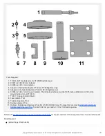
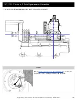
ST, DS - Alignment Correction - Introduction

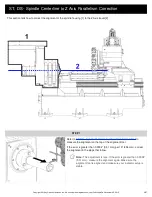
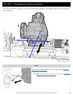
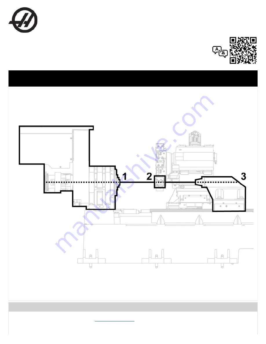
Correct lathe alignment makes a common centerline through the spindle [1], the turret pocket [2], and the tailstock [3] or
secondary spindle. If the turret crashes, the lathe can lose its alignment. This procedure tells you how to correct the lathe
alignment. For clarity, the illustrations hide surrounding components.

Prerequisites

Make sure the machine is level. Refer to the 

Lathe Leveling Video

.

Haas Technical Documentation

ST, DS - Alignment Correction

Scan code to get

the latest version

of this document

Translation

Available

Applies to machines built from: 

June, 2010

Copyright 2018 by Haas Automation, Inc. No unauthorized reproduction | Last Published On November 05, 2015

1/67

Summary of Contents for ST

Page 1: ...how to correct the lathe alignment For clarity the illustrations hide surrounding components Prerequisites Make sure the machine is level Refer to the Lathe Leveling Video Haas Technical Documentatio...

Page 2: ...unt T 0017 7 T 0017 Coaxial Indicator Mount 8 Face Indicator Tool 9 Tailstock Alignment Tool 10 Spindle Alignment Tool 11 Optional Spindle Head Alignment Tool for ST 20 30 DS 30 only To make this tool...

Page 3: ...lignment on the top of the alignment tool If the error is greater than 0 0004 0 01 mm per 10 254 mm correct the alignment in the steps that follow Note This adjustment is rare If the error is greater...

Page 4: ...ly to machines with the Y Axis option STEP 1 Measure the squareness of the Y Axis to the Z Axis Refer to ST DS Y Axis Square to Z Axis Check Note This procedure is very similar to the procedure ST DS...

Page 5: ...steps that follow STEP 4 Jog the Z Axis a small amount to move the indicator away from the spindle You will jog the X and Y Axes to move the turret to get access to the screws There are 16 screws 1 th...

Page 6: ...m STEP 6 Jog the X and Y Axes to move the turret to get access to the 10 screws that attach the saddle to the ballscrew nut housing STEP 7 For some of the screws you must use the access holes in the w...

Page 7: ...the Y Axis the full distance STEP 10 Loosen a small amount the 16 screws 1 that attach the saddle to the linear guide trucks and the 10 screws 2 that attach the saddle to the ballscrew nut housing Not...

Page 8: ...ugh to allow the casting to rotate but tight enough to prevent unwanted movement STEP 12 Note You can choose any one of the 4 corner screws 1 as the pivot screw STEP 13 Remove 1 screw at the corner op...

Page 9: ...in STEP 15 The indicator shows amount and direction of the error STEP 16 Insert a pry bar into the empty screw hole and push the wedge into alignment Copyright 2018 by Haas Automation Inc No unauthori...

Page 10: ...orrection STEP 19 Tighten the 16 screws 1 that attach the saddle to the linear guide trucks Tighten to approximately half of the specified torque For torque values refer to Haas Fastener Torque Specif...

Page 11: ...hten the 10 screws 1 that attach the wedge to the ballscrew nut housing Tighten to approximately half of the specified torque For torque values refer to Haas Fastener Torque Specifications STEP 22 Mea...

Page 12: ...crews 1 that attach the wedge to the linear guide trucks For torque values refer to Haas Fastener Torque Specifications STEP 25 Replace the plugs P N 20 4300 that cover some of the screws Caution With...

Page 13: ...s of the X Axis 1 to the spindle centerline 2 STEP 1 Refer to ST DS X Axis to Z Axis Squareness Check to measure the squareness of X Axis movement to the Spindle Centerline Copyright 2018 by Haas Auto...

Page 14: ...e the coordinate position display We will return to this 0 DIST TO GO position in the steps that follow STEP 4 Jog the Z Axis a small amount to move the indicator away from the spindle Jog the X Axis...

Page 15: ...wedge to the linear guide trucks Note After you loosen the screws tighten them enough to let you control the adjustment but keep them loose enough to let you correct the alignment This is approximatel...

Page 16: ...s the pivot screw STEP 9 Remove 1 screw at the corner opposite to the pivot screw STEP 10 Jog the X Axis and the Z Axis until the DIST TO GO values are 0 Copyright 2018 by Haas Automation Inc No unaut...

Page 17: ...on of the error STEP 12 Insert a pry bar into the screw hole and push the wedge into alignment STEP 13 The wedge moves around the pivot screw Copyright 2018 by Haas Automation Inc No unauthorized repr...

Page 18: ...ately half of the specified torque the 16 screws that attach the wedge to the linear guide trucks For torque values refer to Haas Fastener Torque Specifications STEP 16 Measure the squareness Copyrigh...

Page 19: ...orque values refer to Haas Fastener Torque Specifications STEP 18 Measure the squareness STEP 19 If the alignment is correct torque the 16 screws that attach the wedge to the linear guide trucks For t...

Page 20: ...evious section STEP 22 For machines with a Y Axis the steps to align the X Axis are the same as the previous steps Loosen the 16 screws that attach the wedge to the linear guide trucks and the 8 screw...

Page 21: ...e X Axis movement 2 which is set by the alignment of the turret assembly 3 to the wedge 4 STEP 1 Refer to ST DS Turret to X Axis Parallelism Check to measure the parallelism of the turret to X Axis Co...

Page 22: ...trol the adjustment but keep them loose enough to let you correct the alignment This is approximately 5 10 ft lb 7 14 Nm STEP 4 Tighten 1 screw to approximately 20 ft lb 27 Nm to use as a pivot in the...

Page 23: ...n the right side to raise or lower the turret housing casting on right side STEP 6 For example to raise the turret housing casting on the left side do these steps Loosen the lock nuts STEP 7 Turn the...

Page 24: ...the turret housing casting STEP 9 The turret housing casting turns around the pivot screw STEP 10 Monitor the indicator while you turn the jack screw Copyright 2018 by Haas Automation Inc No unauthor...

Page 25: ...Specifications STEP 12 Measure the alignment STEP 13 If the alignment is correct torque the 4 screws For torque values refer to Haas Fastener Torque Specifications ST DS Toolholders to the Spindle Cen...

Page 26: ...Copyright 2018 by Haas Automation Inc No unauthorized reproduction Last Published On November 05 2015 36 67...

Reviews: