HAAS + SOHN 0545008000000, Equipment Sheet
Get your HAAS + SOHN 0545008000000 Equipment Sheet manual for free download at 88.208.23.73:8080. The comprehensive manual covers everything you need to know about this top-notch product, enabling you to operate and maintain it effortlessly. Enhance your experience with the HAAS + SOHN 0545008000000 by accessing this essential user manual today.
Share
Download


Reviews:
No comments
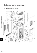
Related manuals for 0545008000000

R11
Brand: Harman Pages: 36

Greta
Brand: PASIAN Pages: 48

Contessa AG DRY
Brand: Firenzo Pages: 11

WANDA
Brand: Nordica Pages: 52

CLESSIDRA ALL STYLE A 11
Brand: Moretti Design Pages: 32

Corner Standing Stove
Brand: Dimplex Pages: 14

GALLERY CLASSIC 5
Brand: Percy Doughty & Co Pages: 9

Murcia Chimenea Large
Brand: La Hacienda Pages: 9

NIMBUS NIM-105N
Brand: Sawotec Pages: 19

14
Brand: ADURO Pages: 92

12
Brand: ADURO Pages: 104

EN13240
Brand: ADURO Pages: 92

2000
Brand: Country Hearth Pages: 24

NPS-1000
Brand: Country Flame Pages: 19

2000 L
Brand: Country Heart Pages: 24

LR-01
Brand: COUNTRY FLAME TECHNOLOGIES Pages: 37

Victoria
Brand: Clarke Pages: 24

MAJESTIC
Brand: Clarke Pages: 28


