
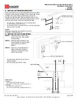

4700 Series Surface Vertical Rod Exit Device
Installation Instructions
Grade 1
I-ED00793
Rev 4, Rev Date: 05/31/2018
Page 1 of 8
Hager Companies 139 Victor Street, St. Louis, MO 63104 (800) 325-9995 www.hagerco.com
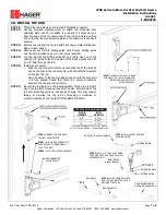
TOOLS REQUIRED
Metal
Wood
Wood and Metal
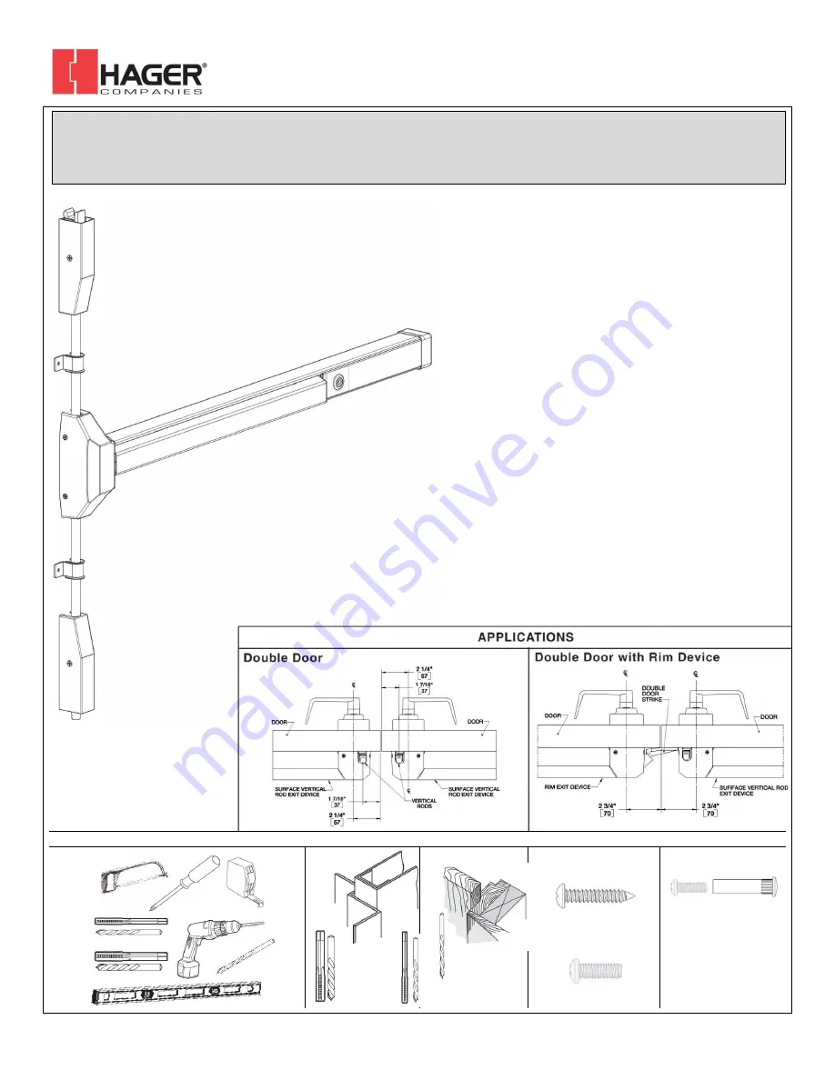
Screws
For wood doors, drill
1/8” hole
Machine Screws
#7 drill, ¼”-20 tap
#16 drill, #12-24 tap
Sex Bolts
Drill 5/16” thru from device
side. Drill 3/8” from other side
(pull side).
Check building and fire codes
to see if your application
requires the use of sleeve
nuts and bolts.
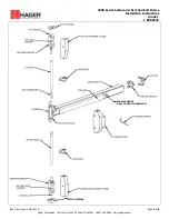
DEVICES COVERED IN THIS DOCUMENT:
4700S Panic Surface Vertical Rod Device
4700L Panic Less Bottom Rod (LBR) Device
4700SF Fire Exit Surface Vertical Rod Device
#16 Drill
#12-24 Tap
#7 Drill
¼”-20 Tap
1/8” Drill


