background image

EQ45 GRADE 1 EXIT TRIM


INSTALLATION INSTRUCTIONS


I

-

ED02734


Rev 1, Rev Date: 01/12/2023


[27390110]


 Page 

1

 of 

8


Hager Companies  139 Victor Street, St. Louis, MO 63104   (800) 325

-

9995   www.hagerco.com


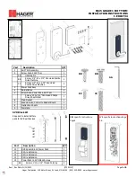
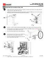
Part


Description


QTY


1


Exit Trim Assembly


1


2


Screw Pack, 4500 Trim


1


AA


Handing Pin


1


BB


Screw, 

1/4”

-

20 

3/4” 

Pan Head Combo 

Drive Machine 


4


CC


Screw, 

1/4”

-

20 

1.25” 

Pan Head 

Combo Drive Machine 


4


3


Power Pack Assy


1


4


AA Batteries


4


5


Screw Pack, Power Pack, Exit Trim


1


Screw, #12 x 

3/4” 

Pan Head Phillips 

Drive Sheet Metal


1


6


Main Gasket


1


7


Wire Harness, Control to Reader Board


1


8


Instruction Sheets


1


9


Template


1


8


9


RIM specific Instructions 
Page4


SVR specific Instructions Page 
5

-

6


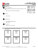
Part


Description


QTY


10


SVR Spacer Block, Power Pack


1


11


6 Wire Extension


1


12


2 Wire Extension


1


13


8 Wire Extension


1


14


Power Pack to SVR Block Screws


1


EE


Screws, #12 x 

1/2” 

Thread Forming


4


SVR Block Kit


Required to install battery 

pack for SVR exit devices


AA


BB


DD


CC


EE


Summary of Contents for EQ45

Page 1: ...chine 4 3 Power Pack Assy 1 4 AA Batteries 4 5 Screw Pack Power Pack Exit Trim 1 Screw 12 x 3 4 Pan Head Phillips Drive Sheet Metal 1 6 Main Gasket 1 7 Wire Harness Control to Reader Board 1 8 Instruc...

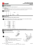
Page 2: ...brasives or harsh chemicals when cleaning or using the lock Required Tools 2 T10 PH2 PH3 OPTIONAL OPTIONAL 3 Prepare Door Skip the prep steps if the door has already been prepared 1 NOTE Drill from bo...

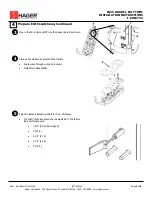
Page 3: ...in the Wire Harness 7 into the Reader Board as shown Prepare Exit Escutcheon Continued 3 Close up escutcheon and install Main Gasket Route wires through wiring hole shown Install Main Gasket 6 4 7 6...

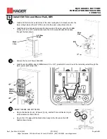
Page 4: ...or using the 4 BB screws 1 4 20 x 3 4 provided and route the 2 Pin wire with black shrink wrap through the hole shown BB 1 5 Install Exit Trim and Power Pack RIM Black 2 Pin All Other Wires Wire Hole...

Page 5: ...black shrink wrap through the hole shown Install Exit Trim and Power Pack SVR 1 Plug the 2 6 and 8 Pin Extension harnesses 11 12 13 into their respective wires in the upper wire bundles Route the exte...

Page 6: ...orientation notes in the holder What happens when batteries installed Lights Sounds Setup Trim 1 SETUP LOCK Setup procedure 2 COMMISSION LOCK GO TO COMMISSIONING PROCEDURE GIVE QR CODE 3 SHOW SELECTIO...

Page 7: ...t on a circuit different from that to which the receiver is connected Consult the dealer or an experienced radio TV technician for help Changes or modifications to the device not expressly approved by...

Reviews: