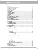
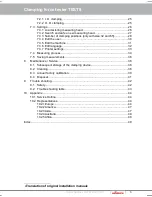
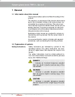
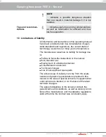
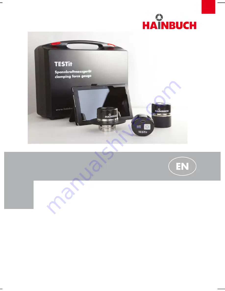
background image

Installation manual

Clamping force tester TESTit

Summary of Contents for TESTit

Page 1: ...Installation manual Clamping force tester TESTit...

Page 2: ...ation 13 3 2 Operating conditions 14 3 3 Type designation 14 4 Structure and function 15 4 1 Overview 15 4 1 1 O D clamping 15 4 1 2 I D clamping 15 4 2 Brief description 16 4 3 Functional description...

Page 3: ...7 Printer settings 33 7 4 Measuring process 34 7 5 Saving measurements 36 8 Maintenance Service 38 8 1 Subsequent storage of the clamping device 38 8 2 Cleaning 38 8 3 Annual factory calibration 39 8...

Page 4: ...roduct It is assumed that the reader is familiar with standard procedures such as cleaning the mounting surfaces 1 2 Explanation of symbols Safety instructions Safety instructions are indicated by sym...

Page 5: ...e The manufacturer assumes no liability for damage due to Failure to follow the instructions in the manual Non intended use Deployment of untrained personnel Unauthorized conversions Technical changes...

Page 6: ...the content are not permitted except for internal use without written ap proval from the manufacturer Actions to the contrary make damage compensation mandatory We reserve the right to enforce additio...

Page 7: ...talling of additional software Software updates Connection with external devices and or net work may influence or even destroy the TESTit soft ware and therefor it is prohibited The warranty for the T...

Page 8: ...requirements WARNING Danger of injury due to insufficient qualifi cation Improper handling of the clamping device can cause serious injury or material damage Only have activities performed by personn...

Page 9: ...they reliably execute their work are considered as person nel Persons whose capability to react is impaired for instance through drugs alcohol or medication are not approved Comply with age specific a...

Page 10: ...sidered to be misuse and can cause dangerous situations WARNING Danger due to misuse Misuse of the TESTit can cause dangerous sit uations Particularly refrain from the following uses of the clamping d...

Page 11: ...d to protect against entanglement by moving machine parts Do not wear rings chains or other jewelry Safety footwear for protection against heavy falling parts and slipping on slippery substrates For s...

Page 12: ...o the environment initiate suitable measures immediately If in doubt notify the responsible municipal authority about the damage The following environmentally harmful substances are used Battery Elect...

Page 13: ...clamping Size 18 32 65 28 50 70 Clamping mm Clamping force max at measuring area kN 3 measuring points 80 140 225 100 200 240 Clamping force max at measuring area kN 2 measuring points 90 150 Speed m...

Page 14: ...In each possible operating condition the maximum draw force and compressive force may not be ex ceeded 3 3 Type designation Fig 1 The type designation is on the TESTit and includes the following infor...

Page 15: ...Clamping force tester TESTit Structure and function 4 Structure and function 4 1 Overview 4 1 1 O D clamping Fig 2 4 1 2 I D clamping Fig 3 Order Hotline 49 7144 907 333 15...

Page 16: ...part can deform The clamping force tester TESTit not only works per fectly in outer diameter and under rotation but also measures with internal diameters exactly the holding force of mandrels The cla...

Page 17: ...an internal measuring unit amplifier In real time the calculated clamping force values are transferred via bluetooth to the tablet The speed of the machine spindle must be taken from the machine contr...

Page 18: ...via the internal bluetooth interface 4 4 2 Measuring head Fig 5 The measuring head is for measuring the clamping force at the assembled clamping device The measuring head is delivered in a size corre...

Page 19: ...tice of lack of conformity 5 2 Storing Under certain circumstances instructions for storage and subsequent storage are affixed to the packages that extend beyond the require ments cited here Comply wi...

Page 20: ...t 1 Start the tablet 2 Wait until all the system settings are fully loaded NOTE For the data connection of the tablet to the measuring head a bluetooth connection is used Depending on the design for e...

Page 21: ...E Display A1 at the measuring head An undamaged and fully charged battery has a holding time of 4 5 hours After an idle time of about 15 minutes the measuring head turns off automatically With a resid...

Page 22: ...steps have to be done 1 Loosen and remove the two mounting screws 1 and remove the two measuring bolts 2 Fig 12 2 Put one of the removed measuring bolts into the mounting point that was free at delive...

Page 23: ...the measuring head from 3 to 2 clamping points the following steps have to be done 1 Loosen and remove the two mounting screws 1 and remove the two measuring bolts 2 Fig 14 2 Put one of the removed m...

Page 24: ...ooth round clamping points Check the surface of the clamping point NOTE While clamping the measuring head may not touch to a work piece end stop or to the man drels body and or housing Check the clamp...

Page 25: ...must be given sufficient reserve stroke 7 2 1 I D clamping Fig 15 To start the inner measurement proceed as follows 1 Assemble the segmented mandrel to the machine 2 Assemble the segmented clamping b...

Page 26: ...measuring head 3 Setting the number of clamping points only with clamping size 32 and 65 4 Add or delete an inspector 5 Add or delete a machine 6 Choose a language german english 7 Printer settings To...

Page 27: ...ring head will be established 7 3 2 Search and safe a new measuring head 5 x To connect a new measuring head proceed as fol lows 1 Switch on the measuring head 2 Switch to the tab Connection 3 Click S...

Page 28: ...rement the new measuring head is available for connection 7 3 3 Number of clamping positions only with size 32 and 65 With the measuring head of size 32 and 65 you have the possibility to choose the n...

Page 29: ...tch into the tab Clamping points 6 Select the wanted and needed number of clamping points 7 Save your selection by clicking on Apply The saved number of clamping positions is now shown on the main tab...

Page 30: ...into the tab Settings 2 Click Add user 3 Enter the name of the user into the opened win dow 4 Confirm with OK 5 Click Save settings The new user is saved and available for later use To delete an exis...

Page 31: ...ck Add machine 3 Enter the name of the machine into the opened window 4 Confirm with OK 5 Confirm again for deleting 6 Click Safe settings The new machine is saved and is available for later use To de...

Page 32: ...The software is available in two languages german english To change the language proceed as follows 1 Switch to the tab Settings 2 Select the wanted language 3 Click Save The selected language is sav...

Page 33: ...two ways for the future PDF printing black with color To set the printer properties proceed as follows 1 Switch to the tab Settings 2 Select the wanted printer setting 3 Click Safe The selected print...

Page 34: ...defined and the connection to the measur ing head must be set up To perform a measurement proceed as follows 1 Switch on the measuring head 2 Switch to the tab Measurement data 3 Select a measuring h...

Page 35: ...easuring NOTE The measured force is displayed With overload Value and bar become red At 5 above the maximum value instead of the measuring value the output text over load is shown Example Overload Ord...

Page 36: ...Measuring 7 5 Saving measurements 5 x The measurement results may be saved in PDF for mat For saving proceed as follows 1 Click Save measurement data Now you auto matically switch to the tab Save 36 O...

Page 37: ...ter in the other fields the needed data e g work piece clamping pressure etc NOTE Select the type of PDF file creation Create a single PDF Create a professional PDF The actual measuring data will be a...

Page 38: ...r measurable signs of wear 8 1 Subsequent storage of the clamping device The clamping force tester TESTit must be cleaned and treated with corrosion protection for subsequent storage see section Clean...

Page 39: ...ervice passport To ensure accuracy the measuring head TESTit must be calibrated annually For the annual factory calibration send the TESTit measuring head and the corresponding service pass port back...

Page 40: ...Clamping force tester TESTit Maintenance Service 40 Order Hotline 49 7144 907 333...

Page 41: ...d should only be disposed of by ap proved specialist companies NOTE Composite materials For disposal clamping devices which include composite materials mineral cast CFK must be returned at HAINBUCH Lo...

Page 42: ...ute the emergen cy stop function of the machine 2 Determine the cause of the fault 3 If correction of the fault requires work in the danger zone put the machine in set up mode 4 Immediately inform the...

Page 43: ...e measuring head Specialist Bluetooth connection is faulty Check the connection of the measuring head and tablet Specialist The tablet does not boot The battery is empty Charge the battery Specialist...

Page 44: ...kauf hainbuch at Internet www hainbuch com Austria GGW Gruber Co GmbH Kolingasse 6 1090 Vienna Phone 43 13107596 0 Fax 43 13107596 31 E Mail office ggwgruber com Internet www ggwgruber com Belgium BIS...

Page 45: ...padopoulos GbR Martinstrasse 68 DE 73061 Ebersbach Fils Phone 49 71635858 530668 Fax 49 716352265 E mail paris papet technologies de Hungary GIMEX Hydraulik GmbH Selyem utca 1 9025 Gy r Phone 36 96525...

Page 46: ...k Internet www tnssro eu Slovenia Elmetool d o o Prvomajska ulica 62 5000 Nova Gorica Phone 386 53303300 Fax 386 53303304 E mail info elmetool si Spain Portugal ATM S L C Gran Bretanya 16 Pol Ind Pla...

Page 47: ...Germantown WI 53022 Phone 1 4143589550 Fax 1 4143589560 E mail sales hainbuchamerica com Internet www hainbuch com USA HAINBUCH America Corp WORKHOLDING TECHNOLOGY W129 N10980 Washington Dr Germantown...

Page 48: ...one 65 63053692 Fax 65 63053699 E mail phillip_lee jjsea com Internet www jjsea com Taiwan GSTC Technology Co Ltd No 418 Youn Chun East 1st Rd Taichung City 40877 Taiwan Phone 88 6423805678 Fax 88 642...

Page 49: ...le application 25 Precondition 24 process 34 Measuring head Conversion 22f O Operating conditions 14 Overview 15 P Personal protective equipment Hard hat 11 Protective gloves 11 Protective goggles 11...

Page 50: ...Clamping force tester TESTit Appendix 50 Order Hotline 49 7144 907 333...

Page 51: ...cuments EN 61000 6 2 Electromagnetic compatibility EMC Part 6 2 2006 03 Generic standards Immunity Industrial Environment EN 61000 6 3 Electromagnetic compatibility EMC Part 6 3 2007 09 Generic standa...

Page 52: ...Box 1262 71667 Marbach Erdmannhauser Strase 57 71672 Marbach Germany Phone 49 7144 907 0 Fax 49 7144 18826 sales hainbuch de www hainbuch com 24h Emergency call 49 7144 907 444 09 2015 Part no 80001 0...

Reviews: