


- 1 -
TABLE OF CONTENTS
HGP-660F
Introduction
……………………...………………………… 3
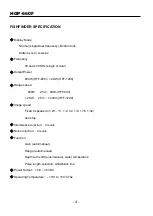
Fishfinder Specification
……………………………………… 4
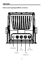
Interconnecting diagram
……………………………………… 5
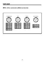
SPEC of the connectors
……………………………………… 6
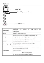
The Keyboard
………………………………………………… 7
Page Select
Page Select
………………………………………………… 8
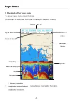
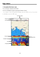
1. Chartplotter/Fishfinder mode ……………………………… 9
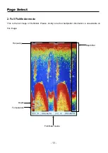
2. Full Fishfinder mode ……………………………………… 11
Operations
Fishfinder 1/2
………………………………………………… 12
Fishfinder 2/2
………………………………………………… 14
Fishfinder Modes ………………………………………………… 16
Installation
1. Display unit Location…………………………………………… 18
2. Display unit Installation………………………………………… 18
3. Power connection.
……………………………………… 19
4. Sensor connection
……………………………………… 19
5. Transducer Installation………………………………………… 20
6. Transom Mounting …………………………………………… 22
7. Transom Transducer Maintenance…………………………… 22