background image


- 1 -

Important Notice


Manual 
Handling 

Keep this manual in a safe place where you can access it quickly. 
This Manual must be passed to a new owner of the HIS-70R when it is 
transferred. 

 
The  Global  Positioning  System  (GPS)  consists  of  a  total  24  GPS  satellites  that  orbit  the  earth, 
enabling  you  to  determine  your  position  anywhere  in  the  world,  24  hours  a  day,  if  you  can  receive 
satellite  signals.  During  actual  navigation,  carefully  compare  the  position  data  with  all  available 
navigation sources  such  as  Loran  C,  Decca,  other  navigators,  charts,  visual  navigation,  depth,  water 
temperature and others. It is your responsibility to make navigation judgments. 


DGPS Operation Note : 

 
Your position can be improved by DGPS correction. However, when you are communicating with other 
ships,  you  may  use  a  DGPS  corrected  position  but  they  may  not.  Make  your  position  source  known 
during communication. 


The Electronic Chart : 
 

Only official authorized charts and notices to mariners contain all the information needed for the safety 
of navigation and, as always remember, the user is responsible for their prudent use. 
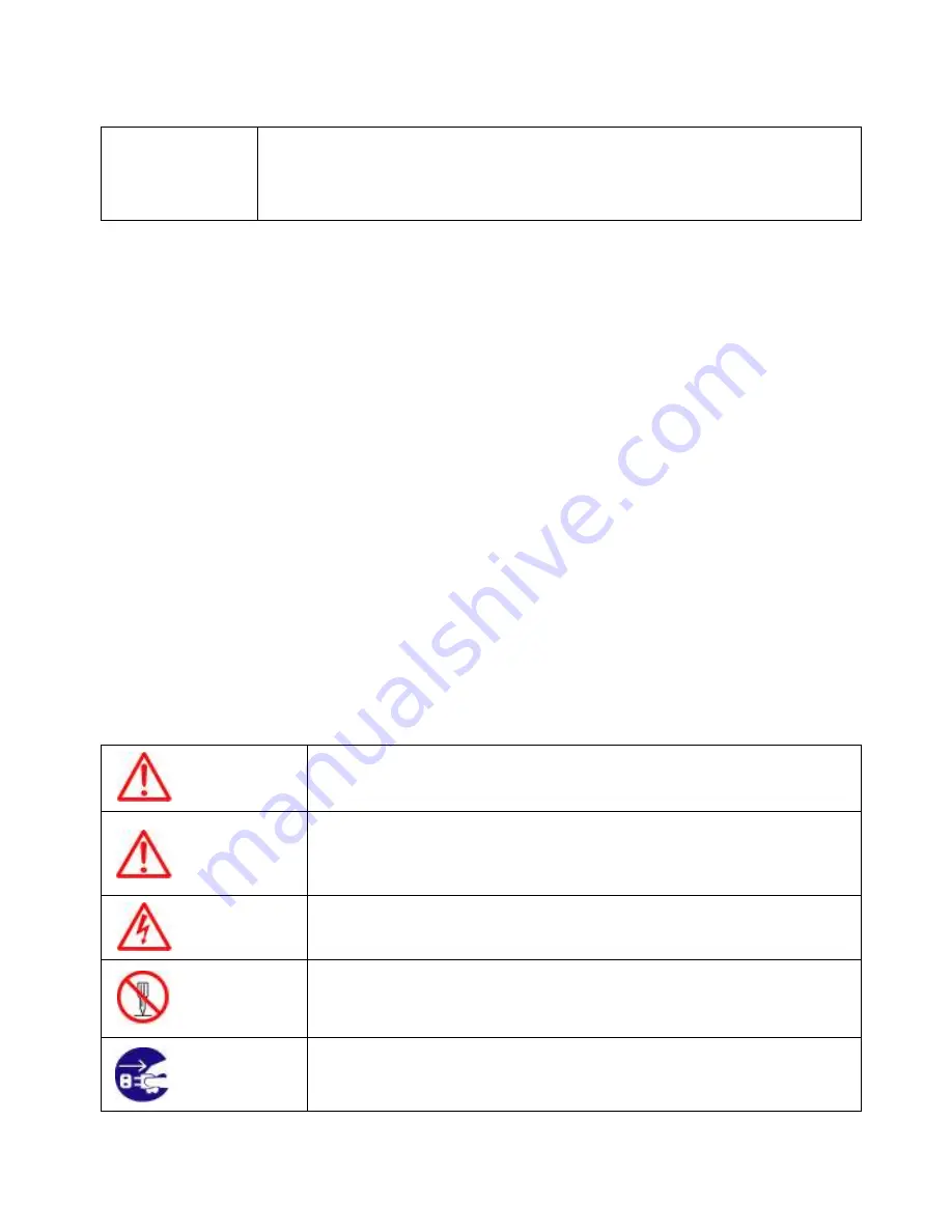


Pictorials 

 
This  manual  uses  the  following  symbols  for  easy  understanding  safety  instructions.  Always  follow 
these instructions carefully. 


WARNING 

Always follow this safety instruction to prevent death or injury. 


CAUTION 

Follow this safety instruction to avoid possible injury or damage to your 
property. 
Symbol “

” is a CAUTION or WARNING label indicating the safety 

instruction. 


WARNING 

This symbol is an Electrical Shock WARNING label. 


Symbol “ ” is an instruction that you must not violate. 
(This symbol instructs NOT to disassemble the system components) 


Symbol “ ” is an operation instruction that you must follow. 
(This symbol shows the main power OFF instruction.) 

Summary of Contents for HIS-70R

Page 1: ...you may use a DGPS corrected position but they may not Make your position source known during communication The Electronic Chart Only official authorized charts and notices to mariners contain all the information needed for the safety of navigation and as always remember the user is responsible for their prudent use Pictorials This manual uses the following symbols for easy understanding safety in...

Page 2: ...t Contact with voltage may cause possible injury or death Do not touch back side of the equipment Harmful line voltage is present on back side of the equipment Never try to touch back side while power is turned on Avoid excessive shock to display unit The LCD display module contains a liquid Do not apply any mechanical shock to the display If the display broken liquid may leak and injure your skin...

Page 3: ...ther heat source as it may malfunction be damaged or burn Use correct power source Operate your system within the specified power voltage An incorrect power supply may cause Maintenance Cautions For Maintenance Personnel Use the following safety precaution internal inspection Discharge capacitors High voltage may be retained in the capacitors if the high tension circuit several minutes after you h...

Page 4: ...maged due to a matching error Consult is for system information Check transducer Connection before power on Do not turn the power switch ON if the transducer is disconnected or if it is not inserted into the water If done the transducer or transmitter circuit may be damaged Always clean the transducer Since transducer performance can drop due to accumulated bottom growth keep the transducer clean ...

Page 5: ...te They are neither verified nor approved by Hydrographic Authorities Electronic charts in HIS 70R are designed only to ease and speed navigation calculations and so must not be relied upon as a primary source of navigation information but rather a backup to the use of official government charts and prudent navigation habits There is no direct relationship between the color of water areas and thei...

Page 6: ... and its wide screen with wide viewing area make placement easy Although HIS 70R offers many advanced features operation is simplified through the use of popup menus similar to those found on personal computers Standard Equipment Configuration List Metal Display unit GPS ANT Power cable Protector Mounting Bracket Knobs Manual ...

Page 7: ... 7 HIS 70R System Standard Equipment Configuration List Plastic Display unit GPS ANT Power cable Protector Mounting Bracket Knobs Manual ...

Page 8: ...S and Sounder Note Sounder option is required is required to use the sounder simulator Simulators are interactive so the front panel keyboard can be used to browse through menus and change setting in the same manner as actual operation The internal simulators allow HIS 70R to operate without having transducers or remote sensors connected However it is necessary to connect the power cable to 12 to ...

Page 9: ...2 73 4 Back up SD Card Optional CHARTPLOTTER SPECIFICATION 1 Display Method Mercado Projection 2 Display Mode True motion North up Course up Head up 3 Latitude Limits Between 85 N to 85 S 4 Map Scale 0 05nm to 1000nm 5 Map Datum WGS 84 Standard 270 different Datums 6 Chart Data C MAP 7 Input Output Data NMEA 0183 GPS RECEIVER GENERAL SPECIFICATION 1 Receive Type L1 frequency 1575 42MHz C A code 2 ...

Page 10: ...MEA 38 4kBaud bi directional 2 VHF Transceiver Transmitter x 1 Receiver x 2 One receiver time shared between AIS and DSC Frequency 156 025 to 162 025 MHz in 25 kHz steps 3 Output Power 33dBm 1 5 dB Channel Bandwidth 25kHz 4 Modulation Modes 25kHz GMSK AIS TX and RX 25kHz AFSK DSC RX only 5 Bit rate 9600 b s 50 ppm GMSK 1200 b s 30 ppm FSK 6 VHF Receiver Sensitivity 107dBm 25kHz Message Error Rate ...

Page 11: ...s BRT PWR shortly and change mode Use the arrow keys of the cursor to change mode KEY Description Cursor Key With MENU Choosing the menu Without MENU Cursor on ENTER Button Enter when menu table on the screen Change the chart of scale MENU One step Quick menu is displayed Two step Main menu is displayed FUNC Setting up Using Frequently key function TRACK Start and stop AIS tracks Vessel tracks WPT...

Page 12: ... 12 HIS 70R System HIS 70R Metal Front Rear Main Screen Keypad Knob Mounting Bracket Connector ...

Page 13: ... 13 HIS 70R System HIS 70R Plastic Front Rear Main Screen Keypad Knob Mounting Bracket Connector ...

Page 14: ... 14 HIS 70R System SPEC of the connectors Metal Plastic ...

Page 15: ...oll through the list to highlight the vessel you wish to go to and press the AIS key The screen will now return to the main chart display and be centred on the vessel you have selected The display also has the ability to TRACK up to 5 different vessels at any one time this feature can be enabled by either selecting a vessel in the list or directly from the TRACK key Select vessel from the list and...

Page 16: ...croll down the list until the type of AIS transmission you want to alter is highlighted in blue pressing the arrow key will scroll you through the choice of icons press the arrow key to go backwards leave your choice of icon showing and press the CLEAR key to exit 5 Filter AIS types This function allows you to turn on or off reception from different types of AIS transmissions for instance if you o...

Page 17: ...at less than a particular speed then switch the Ignore vessels if speed less than function ON and adjust the speed control by use of the keys to the desired value 7 Set up AIS time outs etc This menu controls certain specific AIS functions If repeat transmissions are not received from a vessel after 7 minutes then the target is marked with a X This time can be altered by using the keys If repeat t...

Page 18: ...in the menu with the keys 10 Messages List This window displays lists of specific AIS messages such as Safety Messages that the unit has received Scrolling down the list and highlighting a message allows you to see the contents by pressing the ENTER key Whilst in the main list pressing the MENU key when a message is highlighted will erase that message pressing the keys will allow you to view any o...

Page 19: ... 19 Pages Select Page Press Page key and then go to Pages screen Selectable Pages by red box and then press ENTER key red box ...

Page 20: ...n Press PAGE key on the Pages which selected red box Refer Fig 1 1 1 as below Select the layout of the formation of screen Refer Fig 1 1 2 as below Select displays Refer Fig 1 1 3 1 1 4 as below Fig 1 1 1 Fig 1 1 2 Fig 1 1 3 Fig 1 1 4 ...

Page 21: ...p Customizing Datadar Edit Select the section to edit by red box Refer Fig 1 2 1 as below Press ENTER key and select the data as a user want Refer Fig 1 2 2 as below Finish the formation of data bar press CANCEL key to complete Fig 1 2 1 Fig 1 2 2 ...

Page 22: ...ct the section to edit Refer Fig 1 3 1 as below Press ENTER key and select the data as a user want Refer Fig 1 3 2 as below Finish the formation of data bar press CANCEL key to complete If no navigation data on present activated display it is not available to edit Fig 1 3 1 Fig 1 3 2 ...

Page 23: ...hile the map moves under it 3 Course Up The Course Up mode screen orientation is determined by whether or not navigation is in progress During navigation vessel present position is in the center of the Screen and the course line to the destination is straight up As your present position changes the map moves under the stationary vessel symbol If navigation is stopped the Main Screen appears as Hea...

Page 24: ... of 0 1 3 and 2 3 by the standard of the center of Main Screen The Vessel offset does not work on True Motion 5 Track The Track function provides a record of the path over which your vessel has traveled A track is a series of lines connecting points of vessel present position which are plotted at wither time or distance intervals Tracks are recorded and stored one at a time HIS 70R supports 50 000...

Page 25: ... save the current screen Note The capture file is stored in external SD card The storage location is E9 Capture in SD card Recording time is different by the size of the memory card 14 Navigation 11 1 Previous WPT It is available to set up a previous WPT in the Present preferred route 11 2 Next WPT It is available to set up a next WPT in the Present preferred route 11 3 Route order It is available...

Page 26: ...he waypoint library by any of two different methods You may use the cursor to select locations from a chart or store vessel present position as a waypoint 1 1 1 List Verification of saved WPT information and edit delete navigation Refer the menu from bottom list on the list window 1 1 2 Symbol You can select shape of WPT There are 16 sort of WPT symbols as picture ...

Page 27: ... are 16 sort of WPT symbols as picture 1 2 Route Use waypoints to create a instant route for your sailing The capacity of waypoints are 20 point Every time you put waypoints on the screen the temporary route is drawn on the screen 1 2 1 List Verification of saved Route information and edit delete navigation Refer the menu from bottom list on the list window ...

Page 28: ...3 Track 1 3 1 Color You can select the color of Track There are 16 sort of WPT symbols as picture 1 3 2 Erase You can erase all tracts by the selected color If you want to delete to be being used the track choose All Erase ...

Page 29: ...val is set in time a track displays by track time interval The track time interval and the maximum capacity is 10 000 points The default setting is 10 seconds 1 3 3 4 DIST interval If track interval is set in distance a track displays by track distance interval The track distance interval and the maximum capacity is 10 000 points The default setting is 0 03nm 1 4 Save Userdata You can save the Use...

Page 30: ...ongitude modification 2 5 POG filter Step 1 OFF 59 MAX the POG Filter When it is On over step 1 you can filter the POG of the vessel to optimize it The default setting is incorrect every the country 2 6 COG filter Step 1 OFF 119 MAX the COG Filter When it is On over step 1 you can filter the COG of the vessel to optimize it The default setting is incorrect every the country 2 7 SOG filter Step 1 O...

Page 31: ...fm cf 1m 3 281ft 0 549fm 0 609lfm 0 660jfm The default setting is Meter 3 1 3 TEMP Select desired unit of measure for temperature of water Choose from Celsius or Fahrenheit cf 1 32 3 2 Compass 3 2 1 BRG There is a difference degree where you are in the earth This function is to modify the error from true and Magnetic The default setting is Auto 3 2 2 Variation There could be a difference between t...

Page 32: ...The default setting is on 3 5 Input Output 3 5 1 Output Sentences The chartplotter allows customizing the NMEA 0183 sentence DESCRIPTIONS CONTENTS OF DATA FIELD DEFAULT GPGGA Global Positioning System Fix Data ON GPVTG Course and Ground Speed ON GPZDA Time and Date OFF GPRMB Recommended minimum navigation information OFF GPRMC Recommended Minimum Specific GPS TRANSIT DATA OFF GPAPB Heading track c...

Page 33: ...ar on the display The default setting is shown 3 7 1 2 Position It can change the position of databar The default setting is down 3 7 1 3 Edit It customizes the data bar information 3 7 2 Navigation Data 3 7 2 1 Type It is available to setup the size type on the display The default setting is type1 3 7 2 2 Edit It customizes the Navigation data section 3 7 3 TD Setup It sets Chain Pair ASF ...

Page 34: ... which is necessary for maintenance and upgrade 4 3 MAP VER It contains the version of the chart the datum and the number which is necessary for maintenance and upgrade 4 4 Simulator It is necessary for an indoor demonstration The simulations of GPS AIS in the memory 4 5 Language Select the language 4 6 Initialization 4 6 1 Setup Initialization reset without deleting user data 4 6 1 Factory Initia...

Page 35: ...splay and delete the capture file 5 3 Calendar It is available to check the solar moon calendar and tide 5 4 Key Setup It is available to set up FUNK key and EVENT key on the HD 70F 5 4 1 FUNC key Set the function frequently used for your convenience The default setting is Page FUNC KEY SETUP 1 Page 2 Active 3 Recording 4 Capture ...

Page 36: ... possible to the ones used in the original paper charts 1 4 2 Sunlight It is designed to enhance the visibility of the screen when HIS 70R is exposed to the sunlight The maps are much brighter than in the other displays 1 4 3 NOAA Allows setting NOAA paper chart colors presentation It is available NOAA menu on C_MAP mode 1 5 LAT Modification Though GPS information is accurate there could be an err...

Page 37: ...e depth line on the HY MAP 1 8 1 5 Fishing Banks Setting up the Fishing Banks on the HY MAP The default setting is shown 1 8 1 6 Land Color Select the land color as you want The default setting is yellow 1 8 1 7 Lighthouse Info Setting up the Lighthouse on the HY MAP The default setting is shown 1 8 1 8 EEZ Setting up the EEZ line on the HY MAP 1 8 1 9 Screen Magnification Setting up the Screen Ma...

Page 38: ... not covered by data of the currents level the chartplotter zooms out to the first level covered by cartographic data The default setting is ON The default setting is on 1 8 2 4 Perspective View Chart data may be projected in perspective mode during navigation This function allows setting the panoramic View of the chart As the upper side of the map is more compressed than the lower side a wider ma...

Page 39: ...ing is 270 2 3 Vessel Style Circle Arrow Vessel Select the vessel symbol among Circle Arrow and vessel The default setting is circle 2 4 Orient Resolution Sets you preferred Rolling Road Scale The default setting is 0 3 Alarm 3 1 Navigation 3 1 1 Arrival Alarm When you approach into the waypoint range it gives you a notice with alarm The default setting is OFF 3 1 2 Arrival Radius It is to adjust ...

Page 40: ...2 2 Anchor Radius If you vessel is out of the range of the anchor it gives you notice with alarm The default setting is 0 05nm 3 3 Interval 3 3 1 Interval Alarm It alarms every time you set The default setting is OFF 3 3 2 Interval Time The time is available from one minute until sixty minutes The default setting is 3 min ...

Page 41: ...ion AIS base stations may be employed by the Coastguard port authorities and other authorised bodies AIS units acting as aids to navigation A to Ns can also be fitted to fixed and floating navigation markers such as channel markers and buoys Class A units are a mandatory fit under the safety of life at sea SOLAS convention to vessels above 300 gross tons or which carry more than 11 passengers in I...

Page 42: ...ging course 2 sec Ship 23 Knots 2 sec Ship 23 Knots and changing course 2 sec Ships Static Information 6 min A Class B unit will transmit its MMSI Call Sign and Name length and beam ship type time course over ground COG speed over ground SOG Class B ship borne reporting intervals Ships dynamic conditions Rate Ship with Speed Over the Ground 2 Knots 3 min Ship with Speed Over the Ground 2 Knots 30 ...

Page 43: ...tal number of sentences needed to transfer the message 1 to 9 x2 Sentence number 1 to 9 x3 Sequential message identifier 0 to 9 a AIS Channel A or B s s Encapsulated ITU R M 1371 radio message 4 x Number of fill bits 0 to 5 ACA Message Format The SAS SERIES unit can receive regional channel management information ACA in two ways ITU R M 1371 message 22 or a DSC telecommand received on channel 70 M...

Page 44: ...m number A Alarm condition A Alarm acknowledge state c c Alarm description text Alarms descriptions presented are AIS TX malfunction AIS Antenna VSWR exceeds limit AIS Rx channel 1 malfunction AIS Rx channel 2 malfunction AIS general failure AIS no sensor position in use AIS no valid SOG information AIS no valid COG information AIS 12V alarm AIS 5V alarm AIS Loss of serial interface integrity AIS ...

Page 45: ...orizon As the received GPS signal is very sensitive to noise and interference generated by other onboard transmitters ensure that the GNSS antenna is placed as far away as possible from radar Inmarsat and Iridium transmitters and ensure the GPS antenna is free from direct view of the radar and the Inmarsat beam It is also important that the MF HF and other VHF transmitter antennas are kept as far ...

Page 46: ...terposed between people and the antenna Failure to adhere to these limits could expose persons within the 3 metre radius to RF radiation in excess of the MPE SAR limits HIS 70R brings expandable display technology to your bridge or navigation station A careful installation will assure maximum benefit from HIS 70R integrated features Display Unit Location Select a location for your HIS 70R display ...

Page 47: ...m the bracket and then install lock washers and nuts Tighten securely Install the display unit into the mounting bracket Check alignment and operation of the pivots and security of the mounting Make any adjustments necessary to prevent binding and assure even meshing of the pivot locking washers It is advised to remove the display unit and store it in a safe place to prevent damage during the rest...

Page 48: ...ation is known as NMEA 0183 version 1 5 and version 2 0 NMEA0183 specifications offer many recognized sentences for exchanging data between many types of marine equipment The following technical information is provided for reference and is accurate to the best of our knowledge at the time of printing Please refer to the appropriate NMEA specifications for details and the latest information The dat...

Page 49: ...ition of 3 or 4 satellites and calculating various time differences between transmitted signals the GPS receiver can determine its present position anywhere on earth and thanks to continuous updates calculate speed and course information HOW GPS WORKS Currently the GPS constellation consists of 26 orbiting satellites including 3 spares but this number will increase in the future The GPS receiver c...

Page 50: ...tellites with diameters d1 d2 and d3 Position Fixing Accuracy HDOP The GPS fix accuracy is due to the locations of 3 satellites in the sky High accuracy is obtainable when the satellites are widely scattered in the sky on the contrary accuracy is reduced when the satellites have gathered in a narrow space In the following figure in both cases it is possible to obtain the GPS fix but in the left ca...

Page 51: ...on 1 Keep from a metal 2 Over 4m away from a MF HF ANT VHF or HF whip ANT 3 Over 1 5m upper away from MF HF ANT 4 Over 1m away from a receiving ANT 5 Don t put the GPS ANT into the range of radar s beam Range 30 40 6 Over 1m away from the scanner of the radar 7 Over 5m away from the ANT of the inmarsat 8 Over 3m away form the ANT of the roof 9 Over 2m away from the engine 10 Over 0 5m away from th...

Page 52: ...O DES BY NONE SCALE PER N MODEL CHK BY MATERIAL DRA BY Y S KIM OLIX CO LTD DATE 05 07 2012 Smart7 Series Y S KIM Power Cable S7 DC10303M Y S KIM Y S KIM To HD 70 series J1 16 03P Red Black NOTE 2 1 3 2 1 BLACK RED DC 12 40V ...

Page 53: ... PER N MODEL CHK BY MATERIAL DRA BY Y S KIM OLIX CO LTD DATE 05 07 2012 Smart7 Series Y S KIM Data Cable S7 DC10303M Y S KIM Y S KIM To HD 70 series J1 16 03P Shrinking Tube 20 Shrinking Tube 15 00 7 00 3 00 cut Cable 1 6 5 3 4 2 1 6 5 3 4 2 ...

Page 54: ... 1 2 12 36 FUNCTION PIN WIRE COLOR Power Calbe 2 4 3 5 7 6 8 1 Kim Y S Kim Y S Kim Y S DRA BY Park D J HIS 70A CHK BY PER N DES BY MODEL MATERIAL SCALE 1 2 2012 05 07 DATE OLIX CO LTD S7 DC10301P_A DESCRIPTION DWG NO Power Cable I O ...

Page 55: ... 55 KIM Y S KIM Y S KIM Y S D J PARK S7 PA90101 Smart7 series DESCRIPTION DWG NO DES BY 1 1 SCALE PER N MODEL CHK BY MATERIAL DRA BY GPS ANT OLIX CO LTD DATE 2012 05 07 ...

Page 56: ... 56 Kim Y S Kim Y S Kim Y S Park D J S7 PL00DM_V HIS 70A METAL DESCRIPTION DWG NO DES BY NS SCALE PER N MODEL CHK BY MATERIAL DRA BY OLIX CO LTD DATE 2012 02 16 PLAN DIMENSIONS ...

Page 57: ... 57 PLAN DIMENSIONS 2012 02 16 DATE OLIX CO LTD DRA BY MATERIAL CHK BY MODEL PER N SCALE NS DES BY DWG NO DESCRIPTION HIS 70A PLASTIC S7 PL00DP_V Park D J Kim Y S Kim Y S Kim Y S 1 8 7 3 4 5 2 6 ...

Page 58: ...r a user purchases the product within one 1 year 2 Accessories One 1 year for consumed accessories including TD after a user purchases them Service in Charge 1 Over the term from the guarantee 2 Damage from user s carelessness inundation impact 3 Intentional dismantle modification or remodeling of the unit 4 Unauthorized parts components or accessories are used in the unit 5 Installed or maintaine...

Reviews: