background image

- 1 - 

Important Notice 

Manual 

Handling 

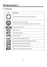
Keep this manual in a safe place where you can access it quickly. 


The Global Positioning System (GPS) consists of a total 24 GPS satellites that orbit the earth, 

enabling you to determine your position anywhere in the world, 24 hours a day, if you can receive 

satellite signals. During actual navigation, carefully compare the position data with all available 

navigation sources such as Loran C, Decca, other navigators, charts, visual navigation, and others. It 

is your responsibility to make navigation judgments. 


The Electronic Chart : 

Only official authorized charts and notices to mariners contain all the information needed for the safety 

of navigation and, as always remember, the user is responsible for their prudent use. 


Pictorials 

This manual uses the following symbols for easy understanding safety instructions. Always follow 
these instructions carefully. 
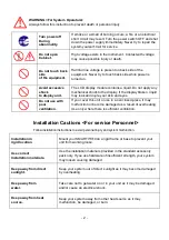
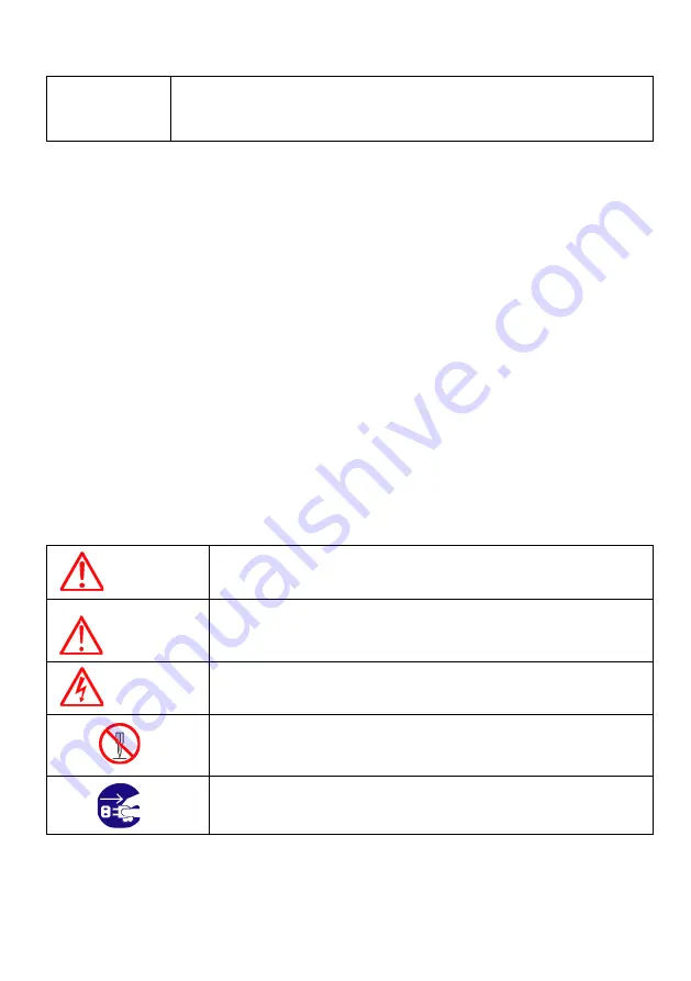


WARNING 

Always follow this safety instruction to prevent death or injury. 


CAUTION 

Follow this safety instruction to avoid possible injury or damage to your 
property. 
Symbol “

” is a CAUTION or WARNING label indicating the safety 

instruction. 


WARNING 

This symbol is an Electrical Shock WARNING label. 


Symbol is an instruction that you must not violate. 
(This symbol instructs NOT to disassemble the system components) 


Symbol is an operation instruction that you must follow. 
(This symbol shows the main power OFF instruction.) 


Summary of Contents for Smart10 Series

Page 1: ...tices to mariners contain all the information needed for the safety of navigation and as always remember the user is responsible for their prudent use Pictorials This manual uses the following symbols for easy understanding safety instructions Always follow these instructions carefully WARNING Always follow this safety instruction to prevent death or injury CAUTION Follow this safety instruction t...

Page 2: ...our skin and eyes Do not use with poor ventilation If you cover this unit or use in an enclosed place it may malfunction or become damaged as a result of overheating Use only where there is sufficient ventilation Installation Cautions For service Personnel Follow installation instructions to avoid personal injury and system malfunction Installation in rigid location Mount your SMART7 8 10on a rigi...

Page 3: ...as not to breath in dust during inspection or cleaning inside your system instruments Operation Notes For operators Observe the following operation notes otherwise the system failure or deterioration can result And periodical inspection and maintenance are required for keeping the system in an optimum condition Backup important data The waypoint and other registered data may become unreadable by u...

Page 4: ... installed by authorized personnel Consult us for transducer installation by authorized personnel WARNING This product is designed to assist navigation When you are sailing use the certified chart from the Government or IMO ...

Page 5: ...ion This device is only an aid to navigation It should be used in conjunction with all other navigation accuracy For safety always resolve any uncertainty before continuing navigation CAUTION The performance of LCD displays are degraded by continuous direct exposure to ultraviolet rays Locate your Smart7 8 10 Display away from direct sunlight When not in use Keep the display covered DISPLAY BREAKA...

Page 6: ... the capability of the navigation source to provide accurate position information This device is only an aid to navigation It should be used in conjunction with all other navigation accuracy For safety always resolve any uncertainty before continuing navigation There is no direct relationship between the color of water areas and their depth The navigator shall always query the area for depth infor...

Page 7: ...sh it off immediately in running water for 15 minutes If the liquid contacts your eyes immediately flush your eyes with running water for 15 minutes Contact a physician if any abnormal symptom is experienced INDICATION NOTICE It is important or warning notice on front of article It is only functions for the HD 50A HD 43A on front of article Keyboard ...

Page 8: ... 8 ...

Page 9: ...end of the everything to confirm a selection or entry Change the chart of scale Open the menu Select the Goto function Selects AIS menus Setting up Using Frequently key function Press to place a waypoint and access the waypoint option Start and stop AIS tracks Vessel tracks Cancel the setting or exists from the menu Power on off brightness and day night mode ...

Page 10: ...1 1 1 1 1 Turn on Switch on 1 1 2 Turn off Keep pressing to switch off 1 1 3 Adjust brightness Pressing Fig 1 1 and controlling the brightness with 1 1 4 Use day night mode Pressing Fig 1 1 and changing the day and night with ...

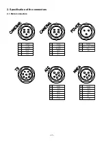
Page 11: ... 11 2 Specification of the connectors 2 1 Metal connectors ...

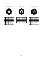
Page 12: ... 12 2 2 Plastic connectors ...

Page 13: ...on Cursor Showing the cursor icon AIS target Showing the received AIS target Databar Showing various data on the top or bottom Sidebar Showing various data on the right or left Cursor INFO The information of the cursor WPT INFO The information of WPT such as LAT LOT Range etc ...

Page 14: ...IS outs ETC AIS Statusbar Showing AIS ClassB RX Channel A Green when receiving to Channel A RX Channel B Green when receiving to Channel B GPS Showing the GPS status Green Receiving Black Out of service TX Green when receiving Class B ...

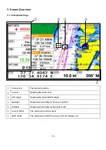
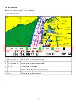
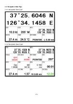
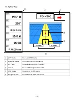
Page 15: ... 15 3 3 Navigation Data Page 3 3 1 Navigation Data Type1 3 3 2 Navigation Data Type2 ...

Page 16: ...ent WPT name Direction of steer The best direction of the steering WPT icon The remaining distance of the WPT Vessel The out of the range from the best XTE Range The range of the XTE alarm Navigation Data The information of the various data ...

Page 17: ... 17 3 5 Steering Page WPT name Name of the WPT Direction of steer The best direction of the steering WPT icon Showing the WPT and the bearing Navigation Data Information of the various data ...

Page 18: ...osition of SAT Position of the satellites SNB Graph Showing the WPT and the bearing Navigation Data Information of the various data Color of the GPS status Black Tracked but no signal Blue Tracked but not used Satellite Green Used Satellite Light Blue SBAS Satellite ...

Page 19: ... 19 ...

Page 20: ...r Mode Databar has three meanings as below 4 1 1 GPS Showing the largest LAT LOT 4 1 2 HY Showing the LAT LOT SOG COG and userdata 4 1 3 NAV You can view detailed information about the of navigation 4 1 4 Customizing Showing various data as what the user wants MENU Advance Setup Customizing Databar Edit ...

Page 21: ... 21 Fig 1 2 1 The databar is coming as Fig 1 2 1 and choose the frame with Four frames are available as Fig 1 2 2 Fig 1 2 2 When choosing the frame setting up in each box as Fig 1 2 3 Fig 1 2 3 ...

Page 22: ...ng the databar position on the top or bottom 5 Cursor 5 1 Calling the cursor Press on the chart the cursor comes out 5 2 Moving Press the cursor is moving to the direction Press together the cursor is moving to Press together the cursor is moving to Press together the cursor is moving to Press together the cursor is moving to 5 3 Removing the cursor Press to remove the cursor 5 4 Cursor informatio...

Page 23: ...dden MENU Advance Setup Customizing INFO window Cursor Cursor information window Shown Hidden 6 Page MENU PAGE Choosing the various pages that set up pages or customized Move the red box to choose the page Fig 1 3 6 1 Page mode Two ways to choose the page 6 1 1 Standard With seeing the set up page choosing the page or modifying 6 1 2 Flip Selected red color ...

Page 24: ... modifying the order is available 6 2 Modify After choosing the page in Fig1 3 keep pressing until the window comes out as Fig 1 3 1 Fig 1 3 1 Choosing the frame with Two frames as Fig 1 3 2 Fig 1 3 2 After choosing the box choose the page as Fig 1 3 3 ...

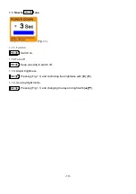
Page 25: ... 25 Fig 1 3 3 When finishing press to exit ...

Page 26: ... 26 7 Active MENU ACTIVE When pressing ACTIVE the red box moves to to chartplotter or fishfinder Selected red color ...

Page 27: ... of Navigation data page 8 1 1 Type1 Large LAT LOT as Fig 1 6 1 Editing the LAT LOT is unavailable 8 1 2 Type2 Various data as Fig 1 6 2 Fig 1 6 1 Fig 1 6 2 8 2 Edit If there is no navigation data on the page editing the navigation data is unavailable MENU Advance Setup Customizing Navigation data Edit After finishing as Fig 1 6 3 press to exit Please refer Customizing for further question ...

Page 28: ... 28 Fig 1 6 3 ...

Page 29: ... 29 9 Memory Card 9 1 Smart10 Inserting the SD micro SD as Fig 1 7 1 Fig 1 7 1 9 2 Smart7 8 Inserting the SD micro SD as Fig 1 7 2 Fig 1 7 2 ...

Page 30: ...me and you will be able to store many WPT in the micro SD 10 2 Route Route can be stored in a micro SD When storing give it a name and you will be able to store many routes in the micro SD 10 3 Track 10 3 1 Type1 Track can be stored in a micro SD When storing give it a name and you will be able to store many tracks in the micro SD 10 3 2 Type2 Track can be stored in a micro SD Index will be a stan...

Page 31: ...ro SD When storing give it a name and you will be able to store many user lines in the micro SD 10 5 User Name User Name can be stored in a micro SD When storing give it a name and you will be able to store many user names in the micro SD ...

Page 32: ...All of WPT in the micro SD show on the list Choose one of them and it will show There are two ways to load WPT First showing the stored WPT as well as the existing on the sceen After loading the stored you will see the window and press Second showing only stored WPT After loading the stored press ENTER 11 2 Route Route loads from the stored micro SD All of route in the micro SD show on the list Ch...

Page 33: ...e stored micro SD Index will be a standard in Type2 After choosing the index stored it 11 4 User Line User line loads from the stored micro SD All of user line in the micro SD show on the list Choose one of them and it will show 11 5 User Name User name loads from the stored micro SD All of user name in the micro SD show on the list Choose one of them and it will show ...

Page 34: ...l and the tracked target based on your vessel s speed and direction and the target s speed and direction TCPA Time to Closest Point of Approach is the time remaining until the CPA will occur Name Name of ship 20 characters MMSI Maritime Mobile Service Identity MMSI number A unique 9 digit number that is assigned to DSC radio station It primarily registers the boat information in the U S Coast Guar...

Page 35: ...leeping target is represented by a small oriented triangle Lost Target When the AIS info is not received from that vessel The presentation will be marked X on the target 3 AIS information window Press ENTER key on Target which wants to see It shows Information of AIS INFO window Fig 2 1 ...

Page 36: ... 36 4 Quick INFO on AIS target Choose AIS information window on Fig 2 1 and AIS data shows under the AIS target Up to four kinds of data is available to choose in Quick INFO ...

Page 37: ... target tracking Up to five Call the cursor and move it on the AIS target as Fig 2 2 and press ro choose the AIS target on the list as Fig 2 3 and press The tracking AIS target is in yellow and on the top of the AIS list Fig 2 2 Fig 2 3 ...

Page 38: ...rlay on the screen On or Off The default setting is On 2 List 2 1 List Fig 2 4 Name Name of the AIS target MMSI MMSI of the AIS target Range Distance between the AIS target and the present position BRG Bearing between the AIS target and the present position Selected blue color ...

Page 39: ... 39 2 2 Detail Choose the AIS target and press ENTER 2 3 Goto Choose the AIS target and press ...

Page 40: ...splay radius Displays range rings centered on your current position The default setting is OFF 4 Display vessels by Color Different types of AIS transmissions can be selected to display different colors of icons on the chart display 5 Display vessels by Type ...

Page 41: ...l sound if a vessel comes within that distance The default setting is OFF 7 2 CPA Range The values allowed are from 0 1nm to 10nm The default setting is OFF 7 3 TCPA Alarm The TCPA alarm is the time that a vessel will take to be in the same position as you currently are The default setting is OFF 7 4 TCPA Range The values allowed are from 1 to 50 min The default setting is 1 min 7 5 Radius Alarm W...

Page 42: ...ou move the cursor in chart mode over an AIS target a box appears showing details of that vessel 9 3 Messages List This window displays lists of specific AIS messages such as Safety Messages that the unit has received Scrolling down the list and highlighting a message allows you to see the contents by pressing the ENTER key Whilst in the main list pressing the MENU key when a message is highlighte...

Page 43: ... default setting is Off 9 5 2 Select name Program the name of Fishing Net 9 5 3 Alarm The alarm goes off when no Fishing net AIS target is in setting range The default setting is Off 9 5 4 Alarm Radius Setup the Fishing net alarm range The default setting is 0 05nm 9 6 Popup Window When the cursor in on the AIS target AIS information window activates automatically The default setting is on 9 7 AIS...

Page 44: ...input vessel data in Fig 2 5 Press to store Fig 2 5 Name Name of the vessel MMSI Inputting the MMSI Inputting the MMSI is available only once Call Sign Inputting Call sign Type of Vessel Inputting the vessel type Refer Type of Vessel Dimensions Inputting the vessel size ...

Page 45: ... 45 ...

Page 46: ... Choose one of them and you will exit If you have one WPT in the route the WPT will be stored If you have more than two all of WPT and the route will be stored together 1 2 Goto type2 1 2 1 Setting MENU Navigation Goto type type2 Direct GOTO where you want to go Only one destination is available 1 2 2 Exit Store If you want to exit remove the cursor and press GOTO The window to store or not shows ...

Page 47: ...me Name of the WPT Symbol Symbol of the WPT Color Color of the WPT Latitude Longitude LAT LOT of the WPT Depth Depth of the WPT Bearing Bearing between the WPT and the present position Range Distance between the WPT and the present position Date Time Date and time of the WPT when stored 2 2 Setting the WPT symbol MENU WPT Symbol Selected blue color ...

Page 48: ...how when inputting WPT 2 3 Setting WPT Color MENU WPT Color Choose the color and press ENTER The chosen color will show when inputting WPT 2 4 Creating 2 4 1 Creating on the list MENU Userdata WPT List Adding WPT with pressing Selected red color Selected red color ...

Page 49: ...ing on the chart Call the cursor and move the position where you want and press The current symbol color show for the WPT 2 5 Erasing 2 5 1 Erasing on the list MENU Userdata WPT List Choose the WPT you want to erase and press 2 5 2 Erasing on the chart Call the cursor and put it on the WPT and press ENTER ...

Page 50: ... on the WPT and press ENTER 2 Choose Move 3 Move the WPT to the position where you want to move and press ENTER 2 8 Navigating 2 8 1 Navigating on the list MENU Userdata WPT List GOTO Choose the WPT on the list and press 2 8 2 Navigating on the chart Call the cursor and move it on the WPT and press ENTER Choose GOTO to start ...

Page 51: ... 51 2 9 Sorting MENU Userdata WPT List MENU Sorting the order of WPT on the list ...

Page 52: ...rdata WPT List Editing the WPT on the list 1 Choose the WPT as the blue and press ENTER 2 Choose the item as the green and you may begin to edit 3 After finishing press to exit Edit Selected green color WPT Selected Blue color ...

Page 53: ...d WPT Name Name of the route Number of WPT Number of WPT in the route Total distance Total distance of the route Display Shown Hidden the route on the chart Date Time Date and time of the WPT when stored Start WPT The beginning of the route End WPT The end of the route ...

Page 54: ... Name of the WPT Symbol Symbol of the WPT Color Color of the WPT Latitude Longitude LAT LOT of the WPT Depth Depth of the WPT Bearing Bearing between the WPT and the present position Range Distance between the WPT and the present position Date Time Date and time of the WPT when stored ...

Page 55: ... Two ways to create route The first uses GOTO type1 and the second is Creating new route on the list 3 3 1 Creating new route on the list MENU Userdata Route List Press on the list to create a route Selected Blue color ...

Page 56: ...oute on the list to edit 3 5 Detail edit MENU Userdata Route List PAGE Choose the route on the list and press The window of Route detail shows 3 5 1 Adding WPT Two ways to add WPT 3 5 1 1 Adding the stored WPT MENU Userdata Route List PAGE MENU Fig 3 1 ...

Page 57: ...irst is to manage the total 50 000 points by colors The second is to divide 50 000 points in five rooms and you can store 10 000 points for the maximum in each room Tracking has two types by time and by distance 4 1 Track on off MENU Track Shown Hidden the track 4 2 Choosing the track 4 2 1 By time MENU Userdata Track Track Setup Record Setup Time Tracking by the set time 4 2 2 Setting the time in...

Page 58: ...ckness MENU Userdata Track Track Setup Thickness Setting the track thickness 4 4 Track Color MENU Track Color Choose the color and press ENTER The number next the color shows the number point of the track color 4 5 Track type 4 5 1 Type1 MENU Userdata Track Track Setup Type1 4 5 1 1 Erasing MENU Userdata Track Erase Selected red color ...

Page 59: ...a Track Erase Press 4 5 2 Type2 MENU Userdata Track Track Setup Type2 4 5 2 1 Select index MENU Userdata Track Select Index Five rooms in the index The maximum is 10 000 points in each room In Type2 storing loading and erasing are available to manage in the room 4 5 2 2 List Showing the information of each room Fig 3 2 List Showing the track room ...

Page 60: ...nd time of the track room when stored Color Color of the track room On Off 선택된 index에 항적 상태를 표시합니다 Display Show Hidden the track room Start Point The beginning of the track room End Point The end of the track room 4 5 2 3 Erasing Choose the track room on the list and press ...

Page 61: ...int B 3 The cursor windows provides the distance and bearing between A and B 4 Press to exit 6 User Line Adding lines directly on the chart 1 Call the cursor 2 Press ENTER and User Line shows 3 Move the cursor to the beginning point and press ENTER 4 Keep moving the cursor and press ENTER each time 5 Press to exit A point B point Range Bearin ...

Page 62: ...nd move it to the point 2 Press ENTER and choose User Name 4 Inputting letters with 5 Press to exit 8 Correction Offset When the chart position is wrong making it correct 1 Call the cursor and move it to the correct position 2 Press ENTER and choose Correction Offset Start point ...

Page 63: ... 63 The maximum range of Correction Offset is 5nm ...

Page 64: ...nter of the Main Screen while the map moves under it 1 3 Course Up MENU Advance Map Setup Map Orientation Up mode The Course Up mode screen orientation is determined by whether or not navigation is in progress During navigation vessel present position is in the center of the Screen and the course line to the destination is straight up As your present position changes the map moves under the statio...

Page 65: ... the display 2 5 Palette It is possible to the palette used to enhance the visibility of the screen depending on the surround light condition The possible choices are listed in the table below 2 5 1 Normal It set the maps are displayed in ordered to use colors as similar as possible to the ones used in the original paper charts 2 5 2 Sunlight It is designed to enhance the visibility of the screen ...

Page 66: ...de 2 9 1 1 Depth Line Setting up 2m 5m 10m 20m 50m of the depth line on the HY MAP 2 9 1 2 Rock Setting up the Rock on the HY MAP The default setting is shown 2 9 1 3 Fishing Banks Setting up the Fishing Banks on the HY MAP The default setting is shown 2 9 1 4 Land Color Select the land color as you want The default setting is yellow 2 9 1 5 Lighthouse Info Setting up the Lighthouse on the HY MAP ...

Page 67: ...then the current level The area covered by the cartographic data read from the previous levels is identified by a dotted pattern When the cursor is moved area not covered by data of the currents level the chartplotter zooms out to the first level covered by cartographic data The default setting is ON The default setting is on 2 9 2 4 Perspective View Chart data may be projected in perspective mode...

Page 68: ...n 3 Vessel 3 1 Vessel Icon Size The size of the present position is adjustable from 0 to 9 The biggest size is 0 The default setting is 9 3 2 Heading Line The length of the heading line is adjustable from 50 until 300 The bigger number the longer line The heading line is used in modes of the true motion and the north up The default setting is 270 3 3 Vessel style Circle Arrow Vessel Select the ves...

Page 69: ...s you a notice with alarm The default setting is OFF 5 1 4 XTE Radius It is to adjust the range of the off course The default setting is 0 25nm 5 2 Anchor 5 2 1 Anchor Alarm It is necessary when your vessel anchors The default setting is OFF 5 2 2 Anchor Radius If you vessel is out of the range of the anchor it gives you notice with alarm The default setting is 0 05nm 5 3 Interval 5 3 1 Interval A...

Page 70: ... 70 5 4 User Line 5 4 1 User Line Alarm It alarms if it breaks into the setting area The default setting is OFF 5 4 2 User Line Radius It sets the range of the course alarm The default setting is 0 05nm ...

Page 71: ... 71 ...

Page 72: ...he latitude modification 1 4 LOT Modification There could be a receiving signal error from satellites If it is on the longitude modify in the longitude modification 1 5 Smoothing setup How to set the calculation of Smoothng OFF No use Mode 1 Calcalation in short time Mode 2 Calcalation in long time The default setting is incorrect every the country 1 6 COG filtering It sets time by second for aver...

Page 73: ...he menu or units for user s visual confidence 2 1 Unit 2 1 1 DIST Speed Select desired unit of measure for distance and speed Choose from nautical mile knots nm kt kilometer kilometers per hour km kmh yard knot yd kt cf 1nm 1 852km 1kt h 1 852km h less than 1nm display in yard and over 1nm display in mile The default setting is Nm Kt 2 1 2 Depth Select desired unit of measure for depth of water Ch...

Page 74: ...ult setting is incorrect every the country 2 3 2 Time Format Sets you preferred time between 12 hour or 24 hour The default setting is 12 hour 2 3 3 Date Format Sets you preferred date among YY MM DD MM DD YY or DD MM YY The default setting is YY MM DD 2 3 4 Month format Sets you preferred date between Character or Number 2 3 5 Calendar setup 2 3 5 1 Week starts on You can select the first day of ...

Page 75: ...OFF GPBOD Bearing origin to destination OFF GPBWC Bearing and distance to waypoint ON SYPLT Samyoung autopilot OFF 2 4 2 Transmit Available to adjust transmit speed of input output in each ports 2 4 3 Buzzer It is can be buzzer on off The default setting is on 2 4 4 Backlight time out It is the screen sets the time to sleep mode The default setting is off 2 4 5 Customizing 2 4 5 1 Databar 2 4 5 1 ...

Page 76: ... section except activated the echo sounder section 2 4 5 3 1 Display Shown Hidden Sidebar The default setting is off 2 4 5 3 2 Position Choosing the position of Sidebar on the right and left The default setting is left 2 4 5 3 3 Edit Editing Sidebar 2 4 5 4 Menu 2 4 5 4 1 Type Two kinds of Menu HGP and Smart The default setting is smart 2 4 5 4 2 Color Changing the menu color The default setting i...

Page 77: ...those will show on the track color window 2 4 5 6 Page mode It is a select the page mode Standard Choosing Page and customizing is available Flip Showing the chosen pages in order The default setting is Standard 2 4 6 TD Setup It sets Chain Pair ASF 3 Maintenance It is necessary to check the system or the version for maintenance and demonstrate Smart7 8 10 serieswith the simulators 3 1 Program Ver...

Page 78: ... 3 6 1 User Initialization The stored setting is initialized in the user setting 3 6 1 Setup Initialization reset without deleting user data 3 6 2 Factory Initialization returning to the initial system from the releasing of factory All user data will be deleted 4 Others 4 1 Screen capture This is the function of save the current screen Note The capture file is stored in external SD card The storag...

Page 79: ... 79 ...

Page 80: ...on N S E W up Course up Head up 3 Latitude Limits Between 85 N to 85 S 4 Map Scale 0 05nm to 1500nm 5 Map Datum WGS 84 6 Waypoint 30 000 points Total of 16 colors and 16 icons are selectable each point with name tag 8 alphanumeric characters 7 Track Point 50 000 points 2 types 8 Route Max capacity 100 Routes 20 WPTs per each Route Each with name tags 8 alphanumeric characters 9 Draw Point 1 000 po...

Page 81: ...or rate 20 7 Display stats ON TX RX1 RX2 8 Compliant with IEC62287 1 ClassB ITU RM 1371 1 IEC61162 1 EN 60945 9 Output power 2W 33dBm 1 5dB 10 Demodulation GMSK Standard Equipment Configuration List Display unit External GPS ANT option Manual Protector Mounting Bracket Knobs Fuse Bolt Power cable ...

Page 82: ...thod Mercado Projection 2 Display Mode True motion N S E W up Course up Head up 3 Latitude Limits Between 85 N to 85 S 4 Map Scale 0 05nm to 1500nm 5 Map Datum WGS 84 6 Waypoint 30 000 points Total of 16 colors and 16 icons are selectable each point with name tag 8 alphanumeric characters 7 Track Point 50 000 points 2 types 8 Route Max capacity 100 Routes 20 WPTs per each Route Each with name tags...

Page 83: ... 83 Standard Equipment Configuration List Display unit External GPS ANT option Manual Protector Mounting Bracket Knobs Fuse Bolt Power cable ...

Page 84: ...n N S E W up Course up Head up 3 Latitude Limits Between 85 N to 85 S 4 Map Scale 0 05nm to 1500nm 5 Map Datum WGS 84 6 Waypoint 30 000 points Total of 16 colors and 16 icons are selectable each point with name tag 8 alphanumeric characters 7 Track Point 50 000 points 2 types 8 Route Max capacity 100 Routes 20 WPTs per each Route Each with name tags 8 alphanumeric characters 9 Draw Point 1 000 poi...

Page 85: ...or rate 20 7 Display stats ON TX RX1 RX2 8 Compliant with IEC62287 1 ClassB ITU RM 1371 1 IEC61162 1 EN 60945 9 Output power 2W 33dBm 1 5dB 10 Demodulation GMSK Standard equipment configuration List Display unit External GPS ANT option Manual Protector Mounting Bracket Knobs Fuse Bolt Power cable ...

Page 86: ...Mode True motion N S E W up Course up Head up 3 Latitude Limits Between 85 N to 85 S 4 Map Scale 0 05nm to 1500nm 5 Map Datum WGS 84 6 Waypoint 30 000 points Total of 16 colors and 16 icons are selectable each point with name tag 8 alphanumeric characters 7 Track Point 50 000 points 2 types 8 Route Max capacity 100 Routes 20 WPTs per each Route Each with name tags 8 alphanumeric characters 9 Draw ...

Page 87: ... 87 Standard equipment configuration List Display unit External GPS ANT option Manual Protector Mounting Bracket Knobs Fuse Bolt Power cable ...

Page 88: ...od Mercado Projection 2 Display Mode True motion N S E W up Course up Head up 3 Latitude Limits Between 85 N to 85 S 4 Map Scale 0 05nm to 1500nm 5 Map Datum WGS 84 6 Waypoint 30 000 points Total of 16 colors and 16 icons are selectable each point with name tag 8 alphanumeric characters 7 Track Point 50 000 points 2 types 8 Route Max capacity 100 Routes 20 WPTs per each Route Each with name tags 8...

Page 89: ...ity 107dBM Message error rate 20 7 Display stats ON TX RX1 RX2 8 Compliant with IEC62287 1 ClassB ITU RM 1371 1 IEC61162 1 EN 60945 9 Output power 2W 33dBm 1 5dB 10 Demodulation GMSK Standard equipment configuration List Display unit External GPS ANT option Manual Protector Mounting Bracket Knobs Fuse Bolt Power cable ...

Page 90: ...od Mercado Projection 2 Display Mode True motion N S E W up Course up Head up 3 Latitude Limits Between 85 N to 85 S 4 Map Scale 0 05nm to 1500nm 5 Map Datum WGS 84 6 Waypoint 30 000 points Total of 16 colors and 16 icons are selectable each point with name tag 8 alphanumeric characters 7 Track Point 50 000 points 2 types 8 Route Max capacity 100 Routes 20 WPTs per each Route Each with name tags 8...

Page 91: ... 91 Standard equipment configuration List Display unit External GPS ANT option Manual Protector Mounting Bracket Knobs Fuse Bolt Power cable ...

Page 92: ...Present water temperature TOT TIME Total Time Total using time VOLTAGE Present voltage unstable voltage shows in red TTG Time To Goal Remaining time to the destination ETA Estimated time of arrival XTE Cross track error W RNG Distance from the present position to the WPT W BRG Bearing between the present position and the WPT W INFO The total number of WPT and shows the WPT symbol color TRACK The t...

Page 93: ... engaged in dredging or underwater operations 34 Vessel engaged in diving operations 35 Vessel engaged in military operations 36 Sailing 37 Pleasure craft 50 Pilot vessel 51 Search and Rescue vessel 52 Tugs 53 Port Tenders 54 Anti pollution vessel 55 Law enforcement vessel 58 Medical transport 60 Passenger ship 70 Cargo ship 80 Tanker ship ...

Page 94: ...nsidered dangerous to surface navigation Marine farm Lighthouse Wreck depth unknown which is considered dangerous to surface navigation Military restricted area into which entry is prohibited Radar transponder beacons Yacht harbor Marina Fishing prohibited Lighted offshore platform Conical buoy nun buoy ogival buoy Oil tanks Can buoy cylindrical buoy Wrecks Spherical buoy Lights Pillar buoy Barrel...

Page 95: ... 95 ...

Page 96: ...he various remote sensors The mounting surface must be flat and solid to support the unit and prevent vibration There should be access to the inside of the surface to permit through bolt fastening for the mounting bracket Display Unit Installation Temporarily install the mounting bracket on the Genesis display unit and place the unit at the selected location CAUTION The Smart7 8 10 series display ...

Page 97: ...he pivots and security of the mounting Make any adjustments necessary to prevent binding and assure even meshing of the pivot locking washers It is advised to remove the display unit and store it in a safe place to prevent damage during the rest of the installation process Mounting Bracket ...

Page 98: ... 98 Smart10 Flush Mounting Smart7 8 Flush Mounting ...

Page 99: ...terminal is not available install an in line fuse holder Care and Cleaning Smart7 8 10 series is made to withstand marine elements but a little care ensures a trouble free life Accumulations of salt and sand if not removed will eventually mar the finish No solvents or harsh cleaners should be used The display unit may be wiped down with a damp cloth while avoiding the display window Be careful not...

Page 100: ...he time of printing Please refer to the appropriate NMEA specifications for details and the latest information The data sentences used by the HGP 660 are as follows Output sentences Descriptions Contents of data field GPGGA Global Positioning System Fix Data GPGLL Geographic Position Latitude Longitude GPGSA GPS DOP and active satellites GPGSV GPS Satellites in View GPVTG Course and Ground Speed G...

Page 101: ...determine your position in relation to a set of satellite o rbiting the earth The GPS constellation of satellites continuously send radio signals containing the precise position for each satellite back to earth By knowing the position of 3 or 4 satellites and calculating various time differences between transmitted signals the GPS receiver can det ermine its present position anywhere on earth and ...

Page 102: ... of the inmarsat 8 Over 3m away form the ANT of the roof 9 Over 2m away from the engine 10 Over 0 5m away from the metal surface Warning Not less than 0 5m away from the metal surface If the environment can t be satisfied from 1 to 10 have NO 10 satisfied and consider the others ...

Page 103: ... that orbit the earth Signals are required from 3 satellites for two dimensional 2D position calculation whilst 4 satellites are required for three dimensional 3D position calculation As mentioned earlier GPS satellites are not geostationary but they are orbiting the earth as illu strated on the following figure The GPS constellation Note that position is repeatedly fixed through the following thr...

Page 104: ...y accurate distances to the satellites using the Spread Spectrum Modulation method Excellence in GPS s position fixing accuracy i s mainly due to this technology 3 When the satellite locations and their distances are known the GPS receiver fixes its own p osition by triangulation The GPS position calculation As illustrated in the previous figure the position is calculated as the meeting point of t...

Page 105: ...on the contrary accuracy is reduced when the satellites have gathered in a narrow space In the follow ing figure in both cases it is possible to obtain the GPS fix but in the left case the accuracy will be higher than the right HDOP The index for position fixing accuracy is called HDOP Horizontal Dilution Of Precision T he smaller the HDOP value the more accurately the position can be fixed ...

Page 106: ...TION DWG NO DES BY NONE SCALE PER N MODEL CHK BY MATERIAL DRA BY Y S KIM OLIX CO LTD DATE 05 07 2012 Smart Series Y S KIM Power Cable S7 DC10303M Y S KIM Y S KIM 16 03P Red Black NOTE 2 1 3 2 1 BLACK RED DC 12 40V ...

Page 107: ... PER N MODEL CHK BY MATERIAL DRA BY Y S KIM OLIX CO LTD DATE 05 07 2012 Smart Sereis Y S KIM Data Cable S7 DC10103M Y S KIM Y S KIM To HD 70 series J2 J3 16 06P Shrinking Tube 20 Shrinking Tube 15 00 7 00 3 00 cut Cable 1 6 5 3 4 2 1 6 5 3 4 2 ...

Page 108: ...ER N MODEL CHK BY MATERIAL DRA BY Y S KIM OLIX CO LTD DATE 03 19 2014 Smart Series Y S KIM AIS Data Cable S7 DC10103A Y S KIM Y S KIM To HD 70 series J2 J3 16 06P Shrinking Tube 20 Shrinking Tube 15 00 7 00 3 00 cut Cable 1 6 5 3 4 2 1 6 5 3 4 2 ...

Page 109: ...NCTION PIN WIRE COLOR Power Calbe 2 4 3 5 7 6 8 1 Kim Y S Kim Y S Kim Y S DRA BY Park D J Smart Series CHK BY PER N DES BY MODEL MATERIAL SCALE 1 2 03 19 2014 DATE OLIX CO LTD S7 DC10301A DESCRIPTION DWG NO Power Cable I O 6 2 5 4 3 7 ...

Page 110: ... 110 KIM Y S KIM Y S KIM Y S D J PARK S7 PA90101 Smart Series DESCRIPTION DWG NO DES BY 1 1 SCALE PER N MODEL CHK BY MATERIAL DRA BY GPS ANT OLIX CO LTD DATE 2012 05 07 ...

Page 111: ... 111 ...

Page 112: ...after a user purchases the product within one 1 year 2 Accessories One 1 year for consumed accessories including TD after a user purchases them Service in Charge 1 Over the term from the guarantee 2 Damage from user s carelessness inundation impact 3 Intentional dismantle modification or remodeling of the unit 4 Unauthorized parts components or accessories are used in the unit 5 Installed or maint...

Reviews: